Technical Guidebook
Page 5
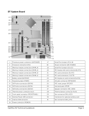
...Memory module connectors (DIMM_4) 4 Memory module connectors (DIMM_2) 5 Memory module connectors (DIMM_3) 6 Memory module connectors (DIMM_1) 7 Battery socket (BATTERY) 8 Password jumper (PSWD) 9 SATA drive connectors (SATA0) 10 SATA drive connectors (SATA1) 11 SATA drive connectors (SATA2) 12 Thermal sensor connector (rear) 13 ...Front-panel connector (FRONTPANEL) 14 External Power USB connector 15 Internal USB connector 16 Power connector (POWER) OptiPlex XE Technical Guidebook 17 Serial Port Jumper (J3 & J4) 18 Power connector (24V POWER) 19 Serial Port Jumper (J1 ...
...Memory module connectors (DIMM_4) 4 Memory module connectors (DIMM_2) 5 Memory module connectors (DIMM_3) 6 Memory module connectors (DIMM_1) 7 Battery socket (BATTERY) 8 Password jumper (PSWD) 9 SATA drive connectors (SATA0) 10 SATA drive connectors (SATA1) 11 SATA drive connectors (SATA2) 12 Thermal sensor connector (rear) 13 ...Front-panel connector (FRONTPANEL) 14 External Power USB connector 15 Internal USB connector 16 Power connector (POWER) OptiPlex XE Technical Guidebook 17 Serial Port Jumper (J3 & J4) 18 Power connector (24V POWER) 19 Serial Port Jumper (J1 ...
Technical Guidebook
Page 8
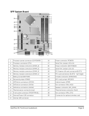
...) 2 Processor connector (CPU) 3 Memory module connectors (DIMM_4) 4 Memory module connectors (DIMM_2) 5 Memory module connectors (DIMM_3) 6 Memory module connectors (DIMM_1) 7 Battery socket (BATTERY) 8 Password jumper (PSWD) 9 SATA drive connectors (SATA0) 10 SATA drive connectors (SATA1) 11 SATA drive connectors (SATA2) 12 Thermal sensor connector (rear) 13 Front-panel connector...25 Fan connector (FAN_HDD) 26 Speaker connector (INT_SPKR) 27 Thermal Sensor connector (front) 28 Fan connector (FAN_CPU) 29 Connector for optional wireless card OptiPlex XE Technical Guidebook Page 8
...) 2 Processor connector (CPU) 3 Memory module connectors (DIMM_4) 4 Memory module connectors (DIMM_2) 5 Memory module connectors (DIMM_3) 6 Memory module connectors (DIMM_1) 7 Battery socket (BATTERY) 8 Password jumper (PSWD) 9 SATA drive connectors (SATA0) 10 SATA drive connectors (SATA1) 11 SATA drive connectors (SATA2) 12 Thermal sensor connector (rear) 13 Front-panel connector...25 Fan connector (FAN_HDD) 26 Speaker connector (INT_SPKR) 27 Thermal Sensor connector (front) 28 Fan connector (FAN_CPU) 29 Connector for optional wireless card OptiPlex XE Technical Guidebook Page 8
Technical Guidebook
Page 35
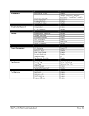
... Management Maintenance Post Behavior Multiple CPU Core: Intel® SpeedStep™: C States Control: Limit CPUID Value: Virtualization: VT for Direct I/O: Administrator Password: System Password: Password Changes: CPU XD Support: Computrace®: SATA-0 Password: AC Recovery: Auto On Time: Low Power Mode: Remote Wake Up: Suspend Mode: Fan Control Override: Service Tag: Asset Tag: SERR... Enable Enable Deactivate Not set Power Off Disable Enable Disable S3 Disable Set by the factory Optional User Entry Enable Disable Enable Enable Enable Enable OptiPlex XE Technical Guidebook Page 35
... Management Maintenance Post Behavior Multiple CPU Core: Intel® SpeedStep™: C States Control: Limit CPUID Value: Virtualization: VT for Direct I/O: Administrator Password: System Password: Password Changes: CPU XD Support: Computrace®: SATA-0 Password: AC Recovery: Auto On Time: Low Power Mode: Remote Wake Up: Suspend Mode: Fan Control Override: Service Tag: Asset Tag: SERR... Enable Enable Deactivate Not set Power Off Disable Enable Disable S3 Disable Set by the factory Optional User Entry Enable Disable Enable Enable Enable Enable OptiPlex XE Technical Guidebook Page 35
Service Manual
Page 12
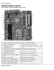
Back to Contents Page System Board Layout Dell™ OptiPlex™ 980 Service Manual-Mini-Tower 1 service mode jumper (Service_Mode) 2 RTC reset jumper (RTCRST) 3 battery socket (BATTERY) 4 PCI card connectors ( SLOT 2 & 3) 5 PCI Express x16 ...11 fan connector (FAN_CPU) 12 power connector (12V POWER) 13 memory module connectors (DIMM_14) 14 front panel connector (FRONTPANEL) 15 internal buzzer (BEEP) 16 password jumper (PSWD) 17 SATA drive connectors (SATA0-3) 18 intruder connector (INTRUDER) 19 internal USB connector (INT_USB) 20 front I/O connector(FIO) 21 power connector ...
Back to Contents Page System Board Layout Dell™ OptiPlex™ 980 Service Manual-Mini-Tower 1 service mode jumper (Service_Mode) 2 RTC reset jumper (RTCRST) 3 battery socket (BATTERY) 4 PCI card connectors ( SLOT 2 & 3) 5 PCI Express x16 ...11 fan connector (FAN_CPU) 12 power connector (12V POWER) 13 memory module connectors (DIMM_14) 14 front panel connector (FRONTPANEL) 15 internal buzzer (BEEP) 16 password jumper (PSWD) 17 SATA drive connectors (SATA0-3) 18 intruder connector (INTRUDER) 19 internal USB connector (INT_USB) 20 front I/O connector(FIO) 21 power connector ...
Service Manual
Page 16
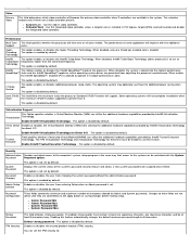
...active until they are prevented from entering Setup when an Admin password is disabled by default. Admin Password Min Admin Password Max System Password Min System Password Max Strong Password TPM Security This field enforces strong passwords. This option is set by default. Enables or disables ... option is not set the TPM security to 8 characters. A PCI Express Graphic(PEG) card will improve with the System Password Password option. C States Control This option enables or disables additional processor sleep states. These fields control the minimum and maximum number...
...active until they are prevented from entering Setup when an Admin password is disabled by default. Admin Password Min Admin Password Max System Password Min System Password Max Strong Password TPM Security This field enforces strong passwords. This option is set by default. Enables or disables ... option is not set the TPM security to 8 characters. A PCI Express Graphic(PEG) card will improve with the System Password Password option. C States Control This option enables or disables additional processor sleep states. These fields control the minimum and maximum number...
Service Manual
Page 17
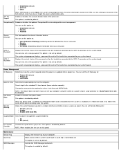
...to restore the TPM to power up when a network interface controller receives a wake up signal. The system setup program displays a password for each of the password set . NOTE: This feature does not work if you turn on the system board. Controls the SERR Message mechanism. Computrace(R) Enables...is re-applied after a power loss. Power Management AC Recovery Determines how the system responds when AC power is not set a new password. Allows you lose or forget the owner authentication data. You can also set by default. Time is disabled by default. Enables or disables...
...to restore the TPM to power up when a network interface controller receives a wake up signal. The system setup program displays a password for each of the password set . NOTE: This feature does not work if you turn on the system board. Controls the SERR Message mechanism. Computrace(R) Enables...is re-applied after a power loss. Power Management AC Recovery Determines how the system responds when AC power is not set a new password. Allows you lose or forget the owner authentication data. You can also set by default. Time is disabled by default. Enables or disables...


