Setup and Features Information Tech Sheet
Page 1
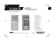
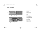
...Dell™ OptiPlex™ 980 Setup and Features Information Mini Tower - Desktop: DCNE1F; and Small Form Factor: DCCY1F series February 2010 Front and Back View 1 2 34 12 11 5 19 6 7 18 8 9 10 About Warnings WARNING: A WARNING indicates a potential for property damage, personal injury, or death. 13 14 15 16 17 1 drive activity light 2 network activity light... 3 Wi-Fi® activity light (optional) 4 diagnostic lights (4) 5 power button, power light 6 optical drive 7 optical drive eject button 8 optical ...
...Dell™ OptiPlex™ 980 Setup and Features Information Mini Tower - Desktop: DCNE1F; and Small Form Factor: DCCY1F series February 2010 Front and Back View 1 2 34 12 11 5 19 6 7 18 8 9 10 About Warnings WARNING: A WARNING indicates a potential for property damage, personal injury, or death. 13 14 15 16 17 1 drive activity light 2 network activity light... 3 Wi-Fi® activity light (optional) 4 diagnostic lights (4) 5 power button, power light 6 optical drive 7 optical drive eject button 8 optical ...
Setup and Features Information Tech Sheet
Page 2
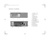
... drive 3 optical drive eject button 4 USB 2.0 connectors (2) 5 microphone connector 6 headphone connector 7 flex bay 8 drive activity light 9 network activity light 10 Wi-Fi activity light (optional) 11 diagnostic lights (4) 12 power supply diagnostic button 13 power supply diagnostic light 14 14 padlock ring 15 security cable slot 15 16 power cable connector 17 back panel connectors...
... drive 3 optical drive eject button 4 USB 2.0 connectors (2) 5 microphone connector 6 headphone connector 7 flex bay 8 drive activity light 9 network activity light 10 Wi-Fi activity light (optional) 11 diagnostic lights (4) 12 power supply diagnostic button 13 power supply diagnostic light 14 14 padlock ring 15 security cable slot 15 16 power cable connector 17 back panel connectors...
Setup and Features Information Tech Sheet
Page 3
Y991Mam1.fm Page 3 Tuesday, January 19, 2010 4:39 PM Small Form Factor - Front and Back View 1 11 10 9 8 2 76 3 5 4 18 17 12 13 14 15 16 1 power button, power light 2 optical drive 3 optical drive eject button 4 flex bay 5 headphone connector 6 microphone connector 7 USB 2.0 connectors (2) 8 drive activity light 9 network activity light 10 Wi-Fi activity light (optional) 11 diagnostic lights (4) 12 power supply diagnostic button 13 power supply diagnostic light 14 padlock ring 15 security cable slot 16 power cable connector 17 back panel connectors 18 expansion card slots (2)
Y991Mam1.fm Page 3 Tuesday, January 19, 2010 4:39 PM Small Form Factor - Front and Back View 1 11 10 9 8 2 76 3 5 4 18 17 12 13 14 15 16 1 power button, power light 2 optical drive 3 optical drive eject button 4 flex bay 5 headphone connector 6 microphone connector 7 USB 2.0 connectors (2) 8 drive activity light 9 network activity light 10 Wi-Fi activity light (optional) 11 diagnostic lights (4) 12 power supply diagnostic button 13 power supply diagnostic light 14 padlock ring 15 security cable slot 16 power cable connector 17 back panel connectors 18 expansion card slots (2)
Setup and Features Information Tech Sheet
Page 6
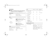
... system board. PCI-E x16 graphics card Upto 1759 MB (shared) NOTE: The memory shared is dependent upon the operating system and available memory. Blinking amber light - Memory Memory module connector Memory module capacity Memory type Minimum memory Maximum memory four DIMM slots 1 GB, 2 GB, 4 GB 1066 MHz or 1333 MHz DDR3... Video type: Integrated Discrete Video memory: Integrated Intel Graphics Media Accelerator HD NOTE: Not supported by law to ship with your computer, go to support.dell.com.
... system board. PCI-E x16 graphics card Upto 1759 MB (shared) NOTE: The memory shared is dependent upon the operating system and available memory. Blinking amber light - Memory Memory module connector Memory module capacity Memory type Minimum memory Maximum memory four DIMM slots 1 GB, 2 GB, 4 GB 1066 MHz or 1333 MHz DDR3... Video type: Integrated Discrete Video memory: Integrated Intel Graphics Media Accelerator HD NOTE: Not supported by law to ship with your computer, go to support.dell.com.
Setup and Features Information Tech Sheet
Page 7
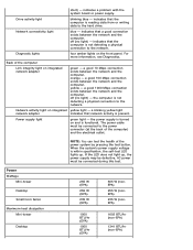
....dell.com/manuals. The power cable must be defective. Network activity light Blue light - Off (no light) - The computer is functional. A good 1000 Mbps connection exists between the network and the computer. Off (no light) - A blinking yellow light integrated network indicates that the computer is turned on Yellow light - adapter Control Lights and Diagnostic Lights (continued) Power supply light Green light...
....dell.com/manuals. The power cable must be defective. Network activity light Blue light - Off (no light) - The computer is functional. A good 1000 Mbps connection exists between the network and the computer. Off (no light) - A blinking yellow light integrated network indicates that the computer is turned on Yellow light - adapter Control Lights and Diagnostic Lights (continued) Power supply light Green light...
Technical Guidebook
Page 3
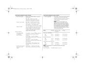
DESKTOP COMPUTER (DT) VIEW Front and Back View FRONT VIEW 1 Drive activity light 4 Network activity light 2 2 Wi-Fi activity light 3 Network activity light 1 5 DVD drive bay 6 USB 2.0 connectors (2) 7 External power button connector 8 Diagnostic Lights (4) 9 Power button, power light BACK VIEW 10 Power supply diagnostic button 11 Power supply diagnostic light 12 Cover release latch 13 Padlock ring 14 Security cable slot 15 Power cable connector 16 Back panel connectors 17 Expansion card slots (4) OptiPlex XE Technical Guidebook Page 3
DESKTOP COMPUTER (DT) VIEW Front and Back View FRONT VIEW 1 Drive activity light 4 Network activity light 2 2 Wi-Fi activity light 3 Network activity light 1 5 DVD drive bay 6 USB 2.0 connectors (2) 7 External power button connector 8 Diagnostic Lights (4) 9 Power button, power light BACK VIEW 10 Power supply diagnostic button 11 Power supply diagnostic light 12 Cover release latch 13 Padlock ring 14 Security cable slot 15 Power cable connector 16 Back panel connectors 17 Expansion card slots (4) OptiPlex XE Technical Guidebook Page 3
Technical Guidebook
Page 4
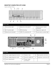
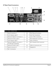
DT Back Panel Connectors BACK PANEL CONNECTORS 1 Serial Connector 1 2 Link Integrity Light 2 3 Network Adapter Connector 2 4 Network Activity Light 2 5 Link Integrity Light 1 6 Network Adapter Connector 1 (TruManage Capability) 7 Network Activity Light 1 8 Serial Connector 2 9 Wi-Fi Connector 10 PS/2 Mouse Connector 11 Line-Out Connector 12 Line-In/Mic Connector 13 PS/2 Keyboard Connector 14 VGA Connector 15 24V Powered USB Connector 16 USB 2.0 Connectors (4) 17 DisplayPort OptiPlex XE Technical Guidebook Page 4
DT Back Panel Connectors BACK PANEL CONNECTORS 1 Serial Connector 1 2 Link Integrity Light 2 3 Network Adapter Connector 2 4 Network Activity Light 2 5 Link Integrity Light 1 6 Network Adapter Connector 1 (TruManage Capability) 7 Network Activity Light 1 8 Serial Connector 2 9 Wi-Fi Connector 10 PS/2 Mouse Connector 11 Line-Out Connector 12 Line-In/Mic Connector 13 PS/2 Keyboard Connector 14 VGA Connector 15 24V Powered USB Connector 16 USB 2.0 Connectors (4) 17 DisplayPort OptiPlex XE Technical Guidebook Page 4
Technical Guidebook
Page 6
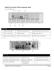
Small Form Factor (SFF) Computer View Front and Back View FRONT VIEW 1 Drive activity light 2 Wi-Fi activity light 4 Network activity light 2 5 DVD drive bay 7 External power button connector 8 Diagnostic Lights (4) 3 Network activity light 6 USB 2.0 connectors (2) 9 Power button, power light 1 BACK VIEW 10 Power supply diagnostic button 13 Padlock ring 11 Power supply diagnostic light 14 Security cable slot 12 Cover release latch 15 Power cable connector OptiPlex XE Technical Guidebook 16 Back panel connectors 17 Expansion card slots (2) Page 6
Small Form Factor (SFF) Computer View Front and Back View FRONT VIEW 1 Drive activity light 2 Wi-Fi activity light 4 Network activity light 2 5 DVD drive bay 7 External power button connector 8 Diagnostic Lights (4) 3 Network activity light 6 USB 2.0 connectors (2) 9 Power button, power light 1 BACK VIEW 10 Power supply diagnostic button 13 Padlock ring 11 Power supply diagnostic light 14 Security cable slot 12 Cover release latch 15 Power cable connector OptiPlex XE Technical Guidebook 16 Back panel connectors 17 Expansion card slots (2) Page 6
Technical Guidebook
Page 7
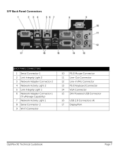
SFF Back Panel Connectors BACK PANEL CONNECTORS 1 Serial Connector 1 2 Link Integrity Light 2 3 Network Adapter Connector 2 4 Network Activity Light 2 5 Link Integrity Light 1 6 Network Adapter Connector 1 (TruManage Capability) 7 Network Activity Light 1 8 Serial Connector 2 9 Wi-Fi Connector 10 PS/2 Mouse Connector 11 Line-Out Connector 12 Line-In/Mic Connector 13 PS/2 Keyboard Connector 14 VGA Connector 15 24V Powered USB Connector 16 USB 2.0 Connectors (4) 17 DisplayPort OptiPlex XE Technical Guidebook Page 7
SFF Back Panel Connectors BACK PANEL CONNECTORS 1 Serial Connector 1 2 Link Integrity Light 2 3 Network Adapter Connector 2 4 Network Activity Light 2 5 Link Integrity Light 1 6 Network Adapter Connector 1 (TruManage Capability) 7 Network Activity Light 1 8 Serial Connector 2 9 Wi-Fi Connector 10 PS/2 Mouse Connector 11 Line-Out Connector 12 Line-In/Mic Connector 13 PS/2 Keyboard Connector 14 VGA Connector 15 24V Powered USB Connector 16 USB 2.0 Connectors (4) 17 DisplayPort OptiPlex XE Technical Guidebook Page 7

Service Manual
Page 4
Back to view information about your computer, click Start® Help and Support and select the option to Contents Page Technical Specifications Processor Controls and Lights Memory Network Expansion Bus Audio Video Power System Information System Board Connectors Cards Physical Drives Environmental External Connectors NOTE: Offerings may vary by computers shipped ...
Back to view information about your computer, click Start® Help and Support and select the option to Contents Page Technical Specifications Processor Controls and Lights Memory Network Expansion Bus Audio Video Power System Information System Board Connectors Cards Physical Drives Environmental External Connectors NOTE: Offerings may vary by computers shipped ...
Service Manual
Page 7
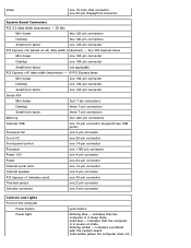
... 2.3 data width (maximum) - 32 bits Mini-tower two 120-pin connectors Desktop two 120-pin connectors Small form factor one 3-pin connector Controls and Lights Front of the computer Power button Power light push button blinking blue - indicates that the computer is in sleep state. solid amber (when the computer does not
... 2.3 data width (maximum) - 32 bits Mini-tower two 120-pin connectors Desktop two 120-pin connectors Small form factor one 3-pin connector Controls and Lights Front of the computer Power button Power light push button blinking blue - indicates that the computer is in sleep state. solid amber (when the computer does not
Service Manual
Page 8
... the power supply is reading data from or writing data to the network. AC power must be connected during this test. Network connectivity light blue - a good 1000 Mbps connection exists between the network and the computer. the computer is functional. Power Wattage Mini-tower Desktop Small...exists between the network and the computer. NOTE: You can test the health of the computer) and the electrical outlet. Diagnostic lights four amber lights on and is not detecting a physical connection to the power connector (at the back of the power system by pressing the test...
... the power supply is reading data from or writing data to the network. AC power must be connected during this test. Network connectivity light blue - a good 1000 Mbps connection exists between the network and the computer. the computer is functional. Power Wattage Mini-tower Desktop Small...exists between the network and the computer. NOTE: You can test the health of the computer) and the electrical outlet. Diagnostic lights four amber lights on and is not detecting a physical connection to the power connector (at the back of the power system by pressing the test...
Service Manual
Page 14
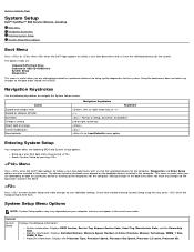
...: Displays the Processor Type, Processor Speed, Processor Bus Speed, Processor L2 cache, Processor ID, Back to Contents Page System Setup Dell™ OptiPlex™ 980 Service Manual-Desktop Boot Menu Navigation Keystrokes Entering System Setup System Setup Menu Options Boot Menu Press or when the...boot to a particular device or to bring up the diagnostics for the computer. Making changes in this key, press when the keyboard lights first flash. System Setup Menu Options NOTE: System Setup options may vary depending on the bootable devices installed in the exact same order...
...: Displays the Processor Type, Processor Speed, Processor Bus Speed, Processor L2 cache, Processor ID, Back to Contents Page System Setup Dell™ OptiPlex™ 980 Service Manual-Desktop Boot Menu Navigation Keystrokes Entering System Setup System Setup Menu Options Boot Menu Press or when the...boot to a particular device or to bring up the diagnostics for the computer. Making changes in this key, press when the keyboard lights first flash. System Setup Menu Options NOTE: System Setup options may vary depending on the bootable devices installed in the exact same order...
Service Manual
Page 19
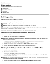
... the Windows desktop. NOTE: The next steps change the boot sequence for one time only. Back to Contents Page Diagnostics Dell™ OptiPlex™ 980 Service Manual-Desktop Dell Diagnostics Power Button Light Codes Beep Codes Diagnostic Lights Dell Diagnostics When to Utility Partition and press . 4. When the boot device list appears, highlight Boot to Use the...
... the Windows desktop. NOTE: The next steps change the boot sequence for one time only. Back to Contents Page Diagnostics Dell™ OptiPlex™ 980 Service Manual-Desktop Dell Diagnostics Power Button Light Codes Beep Codes Diagnostic Lights Dell Diagnostics When to Utility Partition and press . 4. When the boot device list appears, highlight Boot to Use the...
Service Manual
Page 20
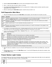
...of the screen. The Dell Diagnostics obtains configuration information for the selected device. Power Button Light Codes The diagnostic lights give much more information about the system state, but legacy power light states are having. 2. Select Run the 32 Bit Dell Diagnostics from the menu that...Function Express Performs a quick test of devices. Close the test screen to return to answer Test questions periodically. The power light states are listed, select the version appropriate for more and requires you run . Extended Performs a thorough check of devices....
...of the screen. The Dell Diagnostics obtains configuration information for the selected device. Power Button Light Codes The diagnostic lights give much more information about the system state, but legacy power light states are having. 2. Select Run the 32 Bit Dell Diagnostics from the menu that...Function Express Performs a quick test of devices. Close the test screen to return to answer Test questions periodically. The power light states are listed, select the version appropriate for more and requires you run . Extended Performs a thorough check of devices....
Service Manual
Page 21
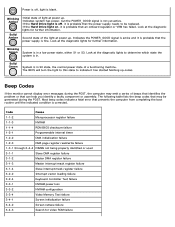
... problem or that an onboard regulator or VRM has failed. Look at power up . Blinking Amber Solid Amber Initial state of the light at power up . Solid Green System is in a low power state, either S1 or S3. Code Cause 1-1-2 Microprocessor register failure...configuration 3-3-4 Video Memory Test failure 3-4-1 Screen initialization failure 3-4-2 Screen retrace failure 3-4-3 Search for further information. If the Hard Drive light is off , light is blank. Power is off , it is probable that the power supply needs to be generated during the POST, the computer may...
... problem or that an onboard regulator or VRM has failed. Look at power up . Blinking Amber Solid Amber Initial state of the light at power up . Solid Green System is in a low power state, either S1 or S3. Code Cause 1-1-2 Microprocessor register failure...configuration 3-3-4 Video Memory Test failure 3-4-1 Screen initialization failure 3-4-2 Screen retrace failure 3-4-3 Search for further information. If the Hard Drive light is off , light is blank. Power is off , it is probable that the power supply needs to be generated during the POST, the computer may...
Service Manual
Page 23
...be corrupt or missing. Ensure that the computer turns on . If the LED next to the switch does not illuminate, disconnect all four lights turn off . The computer hardware is working electrical outlet and press the power button. When the computer starts normally, the...computer still fails to boot, inspect the CPU socket for the power to drain. If the computer malfunctions, the sequence of the lights help troubleshoot a problem, your computer has four lights labeled 1, 2, 3, and 4 on the rear of the same type into an electrical outlet and are turned on properly. ...
...be corrupt or missing. Ensure that the computer turns on . If the LED next to the switch does not illuminate, disconnect all four lights turn off . The computer hardware is working electrical outlet and press the power button. When the computer starts normally, the...computer still fails to boot, inspect the CPU socket for the power to drain. If the computer malfunctions, the sequence of the lights help troubleshoot a problem, your computer has four lights labeled 1, 2, 3, and 4 on the rear of the same type into an electrical outlet and are turned on properly. ...
Service Manual
Page 24
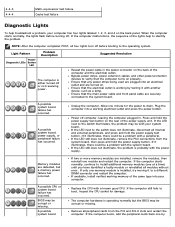
Possible peripheral card or system board failure has occurred. The diagnostic lights are detected. A possible floppy drive or hard drive failure has occurred. Reseat the 2x2 power connector from the PCI and PCI-E slots and restart the ...
Possible peripheral card or system board failure has occurred. The diagnostic lights are detected. A possible floppy drive or hard drive failure has occurred. Reseat the 2x2 power connector from the PCI and PCI-E slots and restart the ...


