Setup and Features Information Tech Sheet
Page 1
Desktop: DCNE1F; Y991Mam1.fm Page 1 Tuesday, January 19, 2010 4:39 PM Dell™ OptiPlex™ 980 Setup and Features Information Mini Tower - and Small Form Factor: DCCY1F series February 2010 Front and Back View 1 2 34 12 11 5 19 6 7 18 8 ...174; activity light (optional) 4 diagnostic lights (4) 5 power button, power light 6 optical drive 7 optical drive eject button 8 optical drive filler panel 9 flex bay 10 USB 2.0 connectors (4) 11 headphone connector 12 microphone connector 13 padlock ring 14 security cable slot 15 power cable connector 16 back panel connectors 17 expansion card...
Desktop: DCNE1F; Y991Mam1.fm Page 1 Tuesday, January 19, 2010 4:39 PM Dell™ OptiPlex™ 980 Setup and Features Information Mini Tower - and Small Form Factor: DCCY1F series February 2010 Front and Back View 1 2 34 12 11 5 19 6 7 18 8 ...174; activity light (optional) 4 diagnostic lights (4) 5 power button, power light 6 optical drive 7 optical drive eject button 8 optical drive filler panel 9 flex bay 10 USB 2.0 connectors (4) 11 headphone connector 12 microphone connector 13 padlock ring 14 security cable slot 15 power cable connector 16 back panel connectors 17 expansion card...
Setup and Features Information Tech Sheet
Page 2
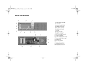
Front and Back View 1 11 10 9 8 7 2 6 3 5 4 12 13 18 17 16 1 power button, power light 2 optical drive 3 optical drive eject button 4 USB 2.0 connectors (2) 5 microphone connector 6 headphone connector 7 flex bay 8 drive activity light 9 network activity light 10 Wi-Fi activity light (optional) 11 diagnostic lights (4) 12 power supply ...
Front and Back View 1 11 10 9 8 7 2 6 3 5 4 12 13 18 17 16 1 power button, power light 2 optical drive 3 optical drive eject button 4 USB 2.0 connectors (2) 5 microphone connector 6 headphone connector 7 flex bay 8 drive activity light 9 network activity light 10 Wi-Fi activity light (optional) 11 diagnostic lights (4) 12 power supply ...
Setup and Features Information Tech Sheet
Page 3
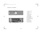
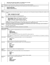
Y991Mam1.fm Page 3 Tuesday, January 19, 2010 4:39 PM Small Form Factor - Front and Back View 1 11 10 9 8 2 76 3 5 4 18 17 12 13 14 15 16 1 power button, power light 2 optical drive 3 optical drive eject button 4 flex bay 5 headphone connector 6 microphone connector 7 USB 2.0 connectors (2) 8 drive activity light 9 network activity light 10 Wi-Fi activity light (optional) 11 diagnostic lights (4) 12 power supply diagnostic button 13 power supply diagnostic light 14 padlock ring 15 security cable slot 16 power cable connector 17 back panel connectors 18 expansion card slots (2)
Y991Mam1.fm Page 3 Tuesday, January 19, 2010 4:39 PM Small Form Factor - Front and Back View 1 11 10 9 8 2 76 3 5 4 18 17 12 13 14 15 16 1 power button, power light 2 optical drive 3 optical drive eject button 4 flex bay 5 headphone connector 6 microphone connector 7 USB 2.0 connectors (2) 8 drive activity light 9 network activity light 10 Wi-Fi activity light (optional) 11 diagnostic lights (4) 12 power supply diagnostic button 13 power supply diagnostic light 14 padlock ring 15 security cable slot 16 power cable connector 17 back panel connectors 18 expansion card slots (2)
Setup and Features Information Tech Sheet
Page 5
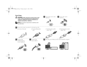
... devices may not be included if you begin any of the following cables: a The blue VGA cable. c The DisplayPort-to -VGA adapter cable. 4 Connect the USB keyboard or mouse (optional). 5 Connect the power cable(s). 6 Press the power buttons on the monitor and the computer. d The DisplayPort-to -DVI adapter cable. b The...
... devices may not be included if you begin any of the following cables: a The blue VGA cable. c The DisplayPort-to -VGA adapter cable. 4 Connect the USB keyboard or mouse (optional). 5 Connect the power cable(s). 6 Press the power buttons on the monitor and the computer. d The DisplayPort-to -DVI adapter cable. b The...
Technical Guidebook
Page 3
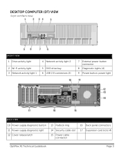
DESKTOP COMPUTER (DT) VIEW Front and Back View FRONT VIEW 1 Drive activity light 4 Network activity light 2 2 Wi-Fi activity light 3 Network activity light 1 5 DVD drive bay 6 USB 2.0 connectors (2) 7 External power button connector 8 Diagnostic Lights (4) 9 Power button, power light BACK VIEW 10 Power supply diagnostic button 11 Power supply diagnostic light 12 Cover release latch 13 Padlock ring 14 Security cable slot 15 Power cable connector 16 Back panel connectors 17 Expansion card slots (4) OptiPlex XE Technical Guidebook Page 3
DESKTOP COMPUTER (DT) VIEW Front and Back View FRONT VIEW 1 Drive activity light 4 Network activity light 2 2 Wi-Fi activity light 3 Network activity light 1 5 DVD drive bay 6 USB 2.0 connectors (2) 7 External power button connector 8 Diagnostic Lights (4) 9 Power button, power light BACK VIEW 10 Power supply diagnostic button 11 Power supply diagnostic light 12 Cover release latch 13 Padlock ring 14 Security cable slot 15 Power cable connector 16 Back panel connectors 17 Expansion card slots (4) OptiPlex XE Technical Guidebook Page 3
Technical Guidebook
Page 4
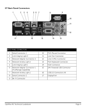
DT Back Panel Connectors BACK PANEL CONNECTORS 1 Serial Connector 1 2 Link Integrity Light 2 3 Network Adapter Connector 2 4 Network Activity Light 2 5 Link Integrity Light 1 6 Network Adapter Connector 1 (TruManage Capability) 7 Network Activity Light 1 8 Serial Connector 2 9 Wi-Fi Connector 10 PS/2 Mouse Connector 11 Line-Out Connector 12 Line-In/Mic Connector 13 PS/2 Keyboard Connector 14 VGA Connector 15 24V Powered USB Connector 16 USB 2.0 Connectors (4) 17 DisplayPort OptiPlex XE Technical Guidebook Page 4
DT Back Panel Connectors BACK PANEL CONNECTORS 1 Serial Connector 1 2 Link Integrity Light 2 3 Network Adapter Connector 2 4 Network Activity Light 2 5 Link Integrity Light 1 6 Network Adapter Connector 1 (TruManage Capability) 7 Network Activity Light 1 8 Serial Connector 2 9 Wi-Fi Connector 10 PS/2 Mouse Connector 11 Line-Out Connector 12 Line-In/Mic Connector 13 PS/2 Keyboard Connector 14 VGA Connector 15 24V Powered USB Connector 16 USB 2.0 Connectors (4) 17 DisplayPort OptiPlex XE Technical Guidebook Page 4
Technical Guidebook
Page 5
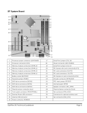
... drive connectors (SATA1) 11 SATA drive connectors (SATA2) 12 Thermal sensor connector (rear) 13 Front-panel connector (FRONTPANEL) 14 External Power USB connector 15 Internal USB connector 16 Power connector (POWER) OptiPlex XE Technical Guidebook 17 Serial Port Jumper (J3 & J4) 18 Power connector (24V POWER) 19 Serial Port Jumper (J1 & J2) 20...
... drive connectors (SATA1) 11 SATA drive connectors (SATA2) 12 Thermal sensor connector (rear) 13 Front-panel connector (FRONTPANEL) 14 External Power USB connector 15 Internal USB connector 16 Power connector (POWER) OptiPlex XE Technical Guidebook 17 Serial Port Jumper (J3 & J4) 18 Power connector (24V POWER) 19 Serial Port Jumper (J1 & J2) 20...
Technical Guidebook
Page 6
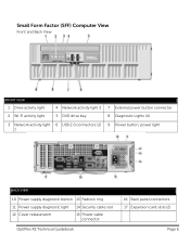
Small Form Factor (SFF) Computer View Front and Back View FRONT VIEW 1 Drive activity light 2 Wi-Fi activity light 4 Network activity light 2 5 DVD drive bay 7 External power button connector 8 Diagnostic Lights (4) 3 Network activity light 6 USB 2.0 connectors (2) 9 Power button, power light 1 BACK VIEW 10 Power supply diagnostic button 13 Padlock ring 11 Power supply diagnostic light 14 Security cable slot 12 Cover release latch 15 Power cable connector OptiPlex XE Technical Guidebook 16 Back panel connectors 17 Expansion card slots (2) Page 6
Small Form Factor (SFF) Computer View Front and Back View FRONT VIEW 1 Drive activity light 2 Wi-Fi activity light 4 Network activity light 2 5 DVD drive bay 7 External power button connector 8 Diagnostic Lights (4) 3 Network activity light 6 USB 2.0 connectors (2) 9 Power button, power light 1 BACK VIEW 10 Power supply diagnostic button 13 Padlock ring 11 Power supply diagnostic light 14 Security cable slot 12 Cover release latch 15 Power cable connector OptiPlex XE Technical Guidebook 16 Back panel connectors 17 Expansion card slots (2) Page 6
Technical Guidebook
Page 7
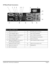
SFF Back Panel Connectors BACK PANEL CONNECTORS 1 Serial Connector 1 2 Link Integrity Light 2 3 Network Adapter Connector 2 4 Network Activity Light 2 5 Link Integrity Light 1 6 Network Adapter Connector 1 (TruManage Capability) 7 Network Activity Light 1 8 Serial Connector 2 9 Wi-Fi Connector 10 PS/2 Mouse Connector 11 Line-Out Connector 12 Line-In/Mic Connector 13 PS/2 Keyboard Connector 14 VGA Connector 15 24V Powered USB Connector 16 USB 2.0 Connectors (4) 17 DisplayPort OptiPlex XE Technical Guidebook Page 7
SFF Back Panel Connectors BACK PANEL CONNECTORS 1 Serial Connector 1 2 Link Integrity Light 2 3 Network Adapter Connector 2 4 Network Activity Light 2 5 Link Integrity Light 1 6 Network Adapter Connector 1 (TruManage Capability) 7 Network Activity Light 1 8 Serial Connector 2 9 Wi-Fi Connector 10 PS/2 Mouse Connector 11 Line-Out Connector 12 Line-In/Mic Connector 13 PS/2 Keyboard Connector 14 VGA Connector 15 24V Powered USB Connector 16 USB 2.0 Connectors (4) 17 DisplayPort OptiPlex XE Technical Guidebook Page 7
Technical Guidebook
Page 8
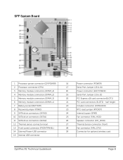
... connector (FAN_HDD) 26 Speaker connector (INT_SPKR) 27 Thermal Sensor connector (front) 28 Fan connector (FAN_CPU) 29 Connector for optional wireless card OptiPlex XE Technical Guidebook Page 8 SFF System Board 1 Processor power connector (12VPOWER) 2 Processor connector (CPU) 3 Memory module connectors (DIMM_4) ... 11 SATA drive connectors (SATA2) 12 Thermal sensor connector (rear) 13 Front-panel connector (FRONTPANEL) 14 External Power USB connector 15 Internal USB connector 16 Power connector (POWER) 17 Serial Port Jumper (J3 & J4) 18 Power connector (24V POWER) 19 Serial...
... connector (FAN_HDD) 26 Speaker connector (INT_SPKR) 27 Thermal Sensor connector (front) 28 Fan connector (FAN_CPU) 29 Connector for optional wireless card OptiPlex XE Technical Guidebook Page 8 SFF System Board 1 Processor power connector (12VPOWER) 2 Processor connector (CPU) 3 Memory module connectors (DIMM_4) ... 11 SATA drive connectors (SATA2) 12 Thermal sensor connector (rear) 13 Front-panel connector (FRONTPANEL) 14 External Power USB connector 15 Internal USB connector 16 Power connector (POWER) 17 Serial Port Jumper (J3 & J4) 18 Power connector (24V POWER) 19 Serial...
Technical Guidebook
Page 14
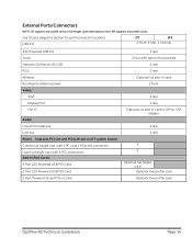
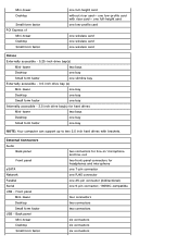
... height riser with 1 PCI and 1 PCIe x16 connector Dual full height riser with 2 PCI connectors Add-In Port Cards: 3 Port 12V Powered USB PCI Card 2 Port 12V Powered USB PCI Card 2 Port Powered Serial PCIe x1 card 1 rear 2 rear with optional riser. External Ports/Connectors NOTE: DT supports low profile cards or... 1 rear Optional via add-in card or DP-to-DVI adapter 1 rear 1 rear X X Optional full height card Optional low profile card Optional low profile card OptiPlex XE Technical Guidebook Page 14 SFF supports low profile cards.
... height riser with 1 PCI and 1 PCIe x16 connector Dual full height riser with 2 PCI connectors Add-In Port Cards: 3 Port 12V Powered USB PCI Card 2 Port 12V Powered USB PCI Card 2 Port Powered Serial PCIe x1 card 1 rear 2 rear with optional riser. External Ports/Connectors NOTE: DT supports low profile cards or... 1 rear Optional via add-in card or DP-to-DVI adapter 1 rear 1 rear X X Optional full height card Optional low profile card Optional low profile card OptiPlex XE Technical Guidebook Page 14 SFF supports low profile cards.
Technical Guidebook
Page 15
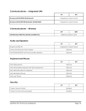
...) Audio and Speakers Realtek ALC269 VB Internal Dell Business Audio Speaker Dell AX510/AX510PA Flat Panel Soundbar Speakers Keyboard and Mouse Dell USB Keyboard Dell USB QuietKey Keyboard with optional palmrest Dell USB Multimedia Pro Keyboard Dell USB Optical Mouse Dell Laser Mouse Security Chassis Intrusion Switch Chassis lock slot and loop support OptiPlex XE Technical Guidebook DT SFF Integrated on system...
...) Audio and Speakers Realtek ALC269 VB Internal Dell Business Audio Speaker Dell AX510/AX510PA Flat Panel Soundbar Speakers Keyboard and Mouse Dell USB Keyboard Dell USB QuietKey Keyboard with optional palmrest Dell USB Multimedia Pro Keyboard Dell USB Optical Mouse Dell Laser Mouse Security Chassis Intrusion Switch Chassis lock slot and loop support OptiPlex XE Technical Guidebook DT SFF Integrated on system...
Technical Guidebook
Page 19
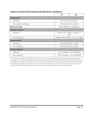
Overcurrent protection polyfuses are used on USB, serial, PS/2, VGA and DP ports, and thermal sensors on CPU, SIO chip, CPU inlet, and PSU inlet for VGA/10u and Serial/15u). OptiPlex XE Technical Guidebook Page 19 The XE motherboard also uses at least 105'C/3000 hrs E-Capacitors or Polymer ... Maximum Altitude Operating -15.2 to 3048 m (-50 to 10,000 ft) Non-Operating -15.2 to 10,668 m (-50 to 35,000 ft) 11The OptiPlex XE is tested to withstand 24x7 operation in 45'C environments standard within 3 year warranty period, and can support 24x7 operation over 3 year warranty period in...
Overcurrent protection polyfuses are used on USB, serial, PS/2, VGA and DP ports, and thermal sensors on CPU, SIO chip, CPU inlet, and PSU inlet for VGA/10u and Serial/15u). OptiPlex XE Technical Guidebook Page 19 The XE motherboard also uses at least 105'C/3000 hrs E-Capacitors or Polymer ... Maximum Altitude Operating -15.2 to 3048 m (-50 to 10,000 ft) Non-Operating -15.2 to 10,668 m (-50 to 35,000 ft) 11The OptiPlex XE is tested to withstand 24x7 operation in 45'C environments standard within 3 year warranty period, and can support 24x7 operation over 3 year warranty period in...
Technical Guidebook
Page 34
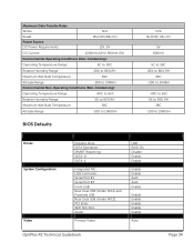
SMART Reporting: SATA-0: SATA-1: Integrated NIC: USB Controller: Serial Port #1: Serial Port #2: Front USB: Rear Dual USB (Under NIC1) and Powered USB: Rear Dual USB (Under NIC2): PCI Slots: WIFI NIC Slot: Audio: Primary Video: USB RAID On Disable Enable Enable Enable Enable Auto Auto Enable Enable Enable Enable Enable Enable Auto OptiPlex XE Technical Guidebook Page 34...
SMART Reporting: SATA-0: SATA-1: Integrated NIC: USB Controller: Serial Port #1: Serial Port #2: Front USB: Rear Dual USB (Under NIC1) and Powered USB: Rear Dual USB (Under NIC2): PCI Slots: WIFI NIC Slot: Audio: Primary Video: USB RAID On Disable Enable Enable Enable Enable Auto Auto Enable Enable Enable Enable Enable Enable Auto OptiPlex XE Technical Guidebook Page 34...
Service Manual
Page 5
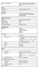
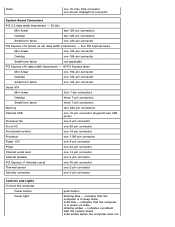
... Network Integrated System Information Chipset DMA channels Interrupt levels BIOS chips (NVRAM) Expansion Bus Bus type Bus speed PCI PCI Express SATA eSATA USB Cards PCI Mini-tower Desktop Small form factor PCI Express x16 (wired as x4) Mini-tower Desktop Small form factor PCI Express x16 ... capable of 10/100/1000 Mb/s communication Intel Q57 Express chipset eight 24 64 Mb and 16 Mb PCI 2.3 PCI Express 2.0 SATA 1.0A and 2.0 eSATA USB 2.0 133 MB/s x1-slot (wireless only) bidirectional speed - 500 MB/s x16-slot (wired as x4) bidirectional speed - 2 GB/s x16-slot bidirectional speed - 8 GB/s ...
... Network Integrated System Information Chipset DMA channels Interrupt levels BIOS chips (NVRAM) Expansion Bus Bus type Bus speed PCI PCI Express SATA eSATA USB Cards PCI Mini-tower Desktop Small form factor PCI Express x16 (wired as x4) Mini-tower Desktop Small form factor PCI Express x16 ... capable of 10/100/1000 Mb/s communication Intel Q57 Express chipset eight 24 64 Mb and 16 Mb PCI 2.3 PCI Express 2.0 SATA 1.0A and 2.0 eSATA USB 2.0 133 MB/s x1-slot (wireless only) bidirectional speed - 500 MB/s x16-slot (wired as x4) bidirectional speed - 2 GB/s x16-slot bidirectional speed - 8 GB/s ...
Service Manual
Page 6
... Express x1 Mini-tower Desktop Small form factor one low-profile card with brackets. External Connectors Audio Back panel Front panel eSATA Network Parallel Serial USB - Back panel Mini-tower Desktop Small form factor two connectors for line-in/ microphone and line-out two front-panel connectors for hard drives Mini... one 9-pin connector; 16550C-compatible four connectors two connectors two connectors six connectors six connectors six connectors Front panel Mini-tower Desktop Small form factor USB - one full-height card without riser card-
... Express x1 Mini-tower Desktop Small form factor one low-profile card with brackets. External Connectors Audio Back panel Front panel eSATA Network Parallel Serial USB - Back panel Mini-tower Desktop Small form factor two connectors for line-in/ microphone and line-out two front-panel connectors for hard drives Mini... one 9-pin connector; 16550C-compatible four connectors two connectors two connectors six connectors six connectors six connectors Front panel Mini-tower Desktop Small form factor USB - one full-height card without riser card-
Service Manual
Page 7
... ATA Mini-tower four 7-pin connectors Desktop three 7-pin connectors Small form factor three 7-pin connectors Memory four 240-pin connectors Internal USB one 10-pin connector (supports two USB ports) Processor fan one 5-pin connector Front I/O one 26-pin connector Front panel control one 14-pin connector Processor one 1156-pin...
... ATA Mini-tower four 7-pin connectors Desktop three 7-pin connectors Small form factor three 7-pin connectors Memory four 240-pin connectors Internal USB one 10-pin connector (supports two USB ports) Processor fan one 5-pin connector Front I/O one 26-pin connector Front panel control one 14-pin connector Processor one 1156-pin...
Service Manual
Page 12
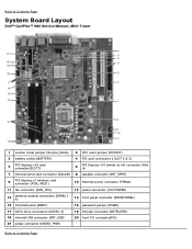
Back to Contents Page System Board Layout Dell™ OptiPlex™ 980 Service Manual-Mini-Tower 1 service mode jumper (Service_Mode) 2 RTC reset jumper (RTCRST) 3 battery socket (BATTERY) 4 PCI card connectors ( SLOT 2 & 3) 5 PCI Express x16 card connector(SLOT1) 6 ... (DIMM_14) 14 front panel connector (FRONTPANEL) 15 internal buzzer (BEEP) 16 password jumper (PSWD) 17 SATA drive connectors (SATA0-3) 18 intruder connector (INTRUDER) 19 internal USB connector (INT_USB) 20 front I/O connector(FIO) 21 power connector (MICRO_PWR) Back to Contents Page
Back to Contents Page System Board Layout Dell™ OptiPlex™ 980 Service Manual-Mini-Tower 1 service mode jumper (Service_Mode) 2 RTC reset jumper (RTCRST) 3 battery socket (BATTERY) 4 PCI card connectors ( SLOT 2 & 3) 5 PCI Express x16 card connector(SLOT1) 6 ... (DIMM_14) 14 front panel connector (FRONTPANEL) 15 internal buzzer (BEEP) 16 password jumper (PSWD) 17 SATA drive connectors (SATA0-3) 18 intruder connector (INTRUDER) 19 internal USB connector (INT_USB) 20 front I/O connector(FIO) 21 power connector (MICRO_PWR) Back to Contents Page
Service Manual
Page 14
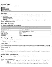
... key, press when the keyboard lights first flash. Back to Contents Page System Setup Dell™ OptiPlex™ 980 Service Manual-Desktop Boot Menu Navigation Keystrokes Entering System Setup System Setup Menu Options Boot Menu Press or when ...the Dell™ logo appears to initiate a one -time boot menu with a list of the valid boot devices for the computer. The options listed are: Onboard SATA Hard Drive Onboard or USB...
... key, press when the keyboard lights first flash. Back to Contents Page System Setup Dell™ OptiPlex™ 980 Service Manual-Desktop Boot Menu Navigation Keystrokes Entering System Setup System Setup Menu Options Boot Menu Press or when ...the Dell™ logo appears to initiate a one -time boot menu with a list of the valid boot devices for the computer. The options listed are: Onboard SATA Hard Drive Onboard or USB...
Service Manual
Page 15
... can set the parallel port to : Enable (default) Disable No boot operating systems with USB support will recognize USB Floppy drives regardless of the integrated parallel port. Identifies and defines the serial port settings. Enables or disables the following onboard devices: Front USB PCI slots Audio OptiPlex ON Reader Rear Quad USB WiFi NIC Slot
... can set the parallel port to : Enable (default) Disable No boot operating systems with USB support will recognize USB Floppy drives regardless of the integrated parallel port. Identifies and defines the serial port settings. Enables or disables the following onboard devices: Front USB PCI slots Audio OptiPlex ON Reader Rear Quad USB WiFi NIC Slot


