
Setup and Features Information Tech Sheet
Page 6
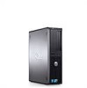
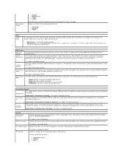
... 4 GB Memory type 1067 MHz DDR3 Minimum memory 1 GB Maximum memory 8 GB Drives Mini Tower Desktop Externally accessible: 3.5 inch drive bays one one 5.25 inch drive bays two one Internally accessible: 3.5 inch SATA drive bays two one Available devices: 3.5 inch SATA hard drives two one 5.25 inch SATA two one DVD-ROM, DVD/CD-RW Combo... are only those required by law to ship with your computer, go to 352 MB shared video memory (with 1 GB system memory) up to support.dell.com.
... 4 GB Memory type 1067 MHz DDR3 Minimum memory 1 GB Maximum memory 8 GB Drives Mini Tower Desktop Externally accessible: 3.5 inch drive bays one one 5.25 inch drive bays two one Internally accessible: 3.5 inch SATA drive bays two one Available devices: 3.5 inch SATA hard drives two one 5.25 inch SATA two one DVD-ROM, DVD/CD-RW Combo... are only those required by law to ship with your computer, go to 352 MB shared video memory (with 1 GB system memory) up to support.dell.com.
Setup and Features Information Tech Sheet
Page 7
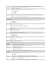
... light indicates power-on the Dell Support website at support.dell.com/manuals. Network connectivity light Green light - The computer is reading data from or writing data to the network. Control Lights and Diagnostic Lights Power button light Green light - Drive activity light Displays the SATA hard drive or optical drive activity. Diagnostic lights Four lights...
... light indicates power-on the Dell Support website at support.dell.com/manuals. Network connectivity light Green light - The computer is reading data from or writing data to the network. Control Lights and Diagnostic Lights Power button light Green light - Drive activity light Displays the SATA hard drive or optical drive activity. Diagnostic lights Four lights...
Guidebook
Page 2
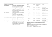
... (NIC 14 Communications - Modem 23 Graphics/Video Controller 24 Hard Drives...27 Optical Drives ...31 BIOS Defaults ...33 Chassis Enclosure & Ventilation Requirements 35 Regulatory Compliance and Environmental 35 Acoustic Noise Emission Information 36 2 DELL™ OPTIPLEX™ 380 TECHNICAL GUIDEBOOK Table of Content THE OPTI Dell™ OptiPlex™ 380 ...3 OptiPlex 380 Technical Specifications 4 Mini Tower Computer (MT) View 4 Desktop Computer...
... (NIC 14 Communications - Modem 23 Graphics/Video Controller 24 Hard Drives...27 Optical Drives ...31 BIOS Defaults ...33 Chassis Enclosure & Ventilation Requirements 35 Regulatory Compliance and Environmental 35 Acoustic Noise Emission Information 36 2 DELL™ OPTIPLEX™ 380 TECHNICAL GUIDEBOOK Table of Content THE OPTI Dell™ OptiPlex™ 380 ...3 OptiPlex 380 Technical Specifications 4 Mini Tower Computer (MT) View 4 Desktop Computer...
Guidebook
Page 3
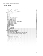
... proven, practical features focused on reducing risk and protecting your organization's energy consumption costs. Achieve outstanding performance with Dell's ProSupport Hard Drive Data Recovery and Certified Data Destruction services. OptiPlex: Secure Computing Made Simple OptiPlex 380 provides basic security offerings to help protect your critical data: Identify breaches to the system chassis using such...
... proven, practical features focused on reducing risk and protecting your organization's energy consumption costs. Achieve outstanding performance with Dell's ProSupport Hard Drive Data Recovery and Certified Data Destruction services. OptiPlex: Secure Computing Made Simple OptiPlex 380 provides basic security offerings to help protect your critical data: Identify breaches to the system chassis using such...
Guidebook
Page 4
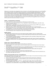
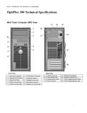
DELL™ OPTIPLEX™ 380 TECHNICAL GUIDEBOOK OptiPlex 380 Technical Specifications Mini Tower Computer (MT) View Front View 1 Optical Drive (optional) 6 Power Button, Power light 2 Optical Drive Eject Button 7 Diagnostic Lights (4) 3 Optical Drive Panel 8 Headphone Connector 4 USB 2.0 Connectors(2) 9 Microphone Connector 5 Hard Drive Activity Light 10 Network Connectivity Light Back View 11 Chassis Lock Loop 12 Cover Release Latch 13 Voltage Selector...
DELL™ OPTIPLEX™ 380 TECHNICAL GUIDEBOOK OptiPlex 380 Technical Specifications Mini Tower Computer (MT) View Front View 1 Optical Drive (optional) 6 Power Button, Power light 2 Optical Drive Eject Button 7 Diagnostic Lights (4) 3 Optical Drive Panel 8 Headphone Connector 4 USB 2.0 Connectors(2) 9 Microphone Connector 5 Hard Drive Activity Light 10 Network Connectivity Light Back View 11 Chassis Lock Loop 12 Cover Release Latch 13 Voltage Selector...
Guidebook
Page 5
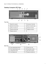
DELL™ OPTIPLEX™ 380 TECHNICAL GUIDEBOOK Desktop Computer (DT) View Front View 1 2 3 4 5 Optical Drive (optional) Optical Drive Eject Button USB 2.0 Connectors (2) Hard Drive Activity Light Diagnostic Lights (4) 6 Power button, Power light 7 Network Connectivity Light 8 Microphone connector 9 Headphone connector Back View 10 Power Supply Diagnostic Button 11 Power Supply Diagnostic Light 12 Voltage selection switch 13 Cover Release Latch 14 Chassis Lock Loop 15 Power Cable Connector 16 Back Panel Connectors 17 Expansion Card Slots (3) 5
DELL™ OPTIPLEX™ 380 TECHNICAL GUIDEBOOK Desktop Computer (DT) View Front View 1 2 3 4 5 Optical Drive (optional) Optical Drive Eject Button USB 2.0 Connectors (2) Hard Drive Activity Light Diagnostic Lights (4) 6 Power button, Power light 7 Network Connectivity Light 8 Microphone connector 9 Headphone connector Back View 10 Power Supply Diagnostic Button 11 Power Supply Diagnostic Light 12 Voltage selection switch 13 Cover Release Latch 14 Chassis Lock Loop 15 Power Cable Connector 16 Back Panel Connectors 17 Expansion Card Slots (3) 5
Guidebook
Page 6
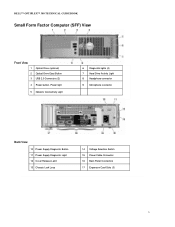
DELL™ OPTIPLEX™ 380 TECHNICAL GUIDEBOOK Small Form Factor Computer (SFF) View Front View 1 Optical Drive (optional) 2 Optical Drive Eject Button 3 USB 2.0 Connectors (2) 4 Power button, Power light 5 Network Connectivity Light 6 Diagnostic lights (4) 7 Hard Drive Activity Light 8 Headphone connector 9 Microphone connector Back View 10 Power Supply Diagnostic Button 11 Power Supply Diagnostic Light 12 Cover Release Latch 13 Chassis Lock Loop 14 Voltage Selection Switch 15 Power Cable Connector 16 Back Panel Connectors 17 Expansion Card Slots (3) 6
DELL™ OPTIPLEX™ 380 TECHNICAL GUIDEBOOK Small Form Factor Computer (SFF) View Front View 1 Optical Drive (optional) 2 Optical Drive Eject Button 3 USB 2.0 Connectors (2) 4 Power button, Power light 5 Network Connectivity Light 6 Diagnostic lights (4) 7 Hard Drive Activity Light 8 Headphone connector 9 Microphone connector Back View 10 Power Supply Diagnostic Button 11 Power Supply Diagnostic Light 12 Cover Release Latch 13 Chassis Lock Loop 14 Voltage Selection Switch 15 Power Cable Connector 16 Back Panel Connectors 17 Expansion Card Slots (3) 6
Guidebook
Page 12
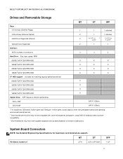
... have write-capable hardware that has been disabled via firmware modifications. DELL™ OPTIPLEX™ 380 TECHNICAL GUIDEBOOK Drives and Removable Storage MT DT SFF Bays: 3.5-inch bay (External Floppy) 1 1 1 (slimline) 5.25-inch bay (External Optical) Hard Drives Supported (Internal) 2 1 1 (slimline) 2 1 x 3.5" or 1 1 x 3.5" or x 2.5" 1 x 2.5" Optical Drives Supported 2 1 1 Interface: SATA (number of 2 FH 2LP or 2FH with some existing...
... have write-capable hardware that has been disabled via firmware modifications. DELL™ OPTIPLEX™ 380 TECHNICAL GUIDEBOOK Drives and Removable Storage MT DT SFF Bays: 3.5-inch bay (External Floppy) 1 1 1 (slimline) 5.25-inch bay (External Optical) Hard Drives Supported (Internal) 2 1 1 (slimline) 2 1 x 3.5" or 1 1 x 3.5" or x 2.5" 1 x 2.5" Optical Drives Supported 2 1 1 Interface: SATA (number of 2 FH 2LP or 2FH with some existing...
Guidebook
Page 17
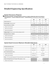
A typical configuration includes: integrated graphics, one hard drive, and one PCIe slots.) Combo Full Height Riser with 1 PCI and 1 PCIe connector (HxL) 1 Height inches/centimeters 4.376/11.115 17 DELL™ OPTIPLEX™ 380 TECHNICAL GUIDEBOOK Detailed Engineering Specifications System Dimensions (Physical) NOTE: System Weight* and Shipping Weight* is based on a typical configuration and may vary.../centimeters 6.6/16.765* 6.6/16.765 Risers: (PCI riser card will replace two PCI slots and Combo riser card will replace one PCI and one optical drive.
A typical configuration includes: integrated graphics, one hard drive, and one PCIe slots.) Combo Full Height Riser with 1 PCI and 1 PCIe connector (HxL) 1 Height inches/centimeters 4.376/11.115 17 DELL™ OPTIPLEX™ 380 TECHNICAL GUIDEBOOK Detailed Engineering Specifications System Dimensions (Physical) NOTE: System Weight* and Shipping Weight* is based on a typical configuration and may vary.../centimeters 6.6/16.765* 6.6/16.765 Risers: (PCI riser card will replace two PCI slots and Combo riser card will replace one PCI and one optical drive.
Guidebook
Page 27
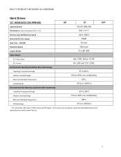
actual capacity varies with preloaded material and operating environment and will be less. DELL™ OPTIPLEX™ 380 TECHNICAL GUIDEBOOK Hard Drives 3.5" 160GB SATA 7200 RPM HDD MT DT Capacity (bytes) 160,041,885,696 Dimensions inches/centimeters (W x H x D) 5.87 x 4 x 1 Interface type and Maximum speed Up to 3Gb/s ...;to 65°C Relative Humidity Range 10% to 90% non-condensing Maximum Wet Bulb Temperature 38°C Altitude Range -50 ft to 35000 ft * For hard drives, GB means 1 billion bytes and TB equals 1 trillion bytes; SFF 27
actual capacity varies with preloaded material and operating environment and will be less. DELL™ OPTIPLEX™ 380 TECHNICAL GUIDEBOOK Hard Drives 3.5" 160GB SATA 7200 RPM HDD MT DT Capacity (bytes) 160,041,885,696 Dimensions inches/centimeters (W x H x D) 5.87 x 4 x 1 Interface type and Maximum speed Up to 3Gb/s ...;to 65°C Relative Humidity Range 10% to 90% non-condensing Maximum Wet Bulb Temperature 38°C Altitude Range -50 ft to 35000 ft * For hard drives, GB means 1 billion bytes and TB equals 1 trillion bytes; SFF 27
Guidebook
Page 33
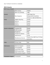
Onboard SATA Hard Drive Onboard or USB CD-ROM Drive Disable Enable Enable Enable System Configuration Integrated NIC: USB Controller: Parallel Port Parallel Port Address Serial Port #1: Miscellaneous Devices Enable Enable ... Limit CPUID Value HDD Acoustic Mode HDD protection Support Enable Enable Disable Bypass Disable Virtualization Support Virtualization Enable 33 DELL™ OPTIPLEX™ 380 TECHNICAL GUIDEBOOK BIOS Defaults BIOS Factory Defaults General BIOS address BIOS chip (NVRAM) Boot Sequence Drives SMART Reporting: SATA-0: SATA-1: SATA-2: F0000h 16Mb USB Floppy...
Onboard SATA Hard Drive Onboard or USB CD-ROM Drive Disable Enable Enable Enable System Configuration Integrated NIC: USB Controller: Parallel Port Parallel Port Address Serial Port #1: Miscellaneous Devices Enable Enable ... Limit CPUID Value HDD Acoustic Mode HDD protection Support Enable Enable Disable Bypass Disable Virtualization Support Virtualization Enable 33 DELL™ OPTIPLEX™ 380 TECHNICAL GUIDEBOOK BIOS Defaults BIOS Factory Defaults General BIOS address BIOS chip (NVRAM) Boot Sequence Drives SMART Reporting: SATA-0: SATA-1: SATA-2: F0000h 16Mb USB Floppy...
Service Manual
Page 3
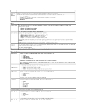
...default) USB Controller Parallel Port Enables or disables the integrated USB controller. l Onboard or USB Floppy l Hard drive (lists the model number of the hard drive currently installed in this list. SATA Operation configures the operating mode of this computer. System Configuration Integrated NIC ...time. The "USB Controller" Setup option will recognize USB Floppy drives regardless of the integrated hard drive controller. All floppy drive are booting on an OS located on every boot l Legacy = The hard drive controller is configured for legacy mode Legacy mode provides for FlexBay...
...default) USB Controller Parallel Port Enables or disables the integrated USB controller. l Onboard or USB Floppy l Hard drive (lists the model number of the hard drive currently installed in this list. SATA Operation configures the operating mode of this computer. System Configuration Integrated NIC ...time. The "USB Controller" Setup option will recognize USB Floppy drives regardless of the integrated hard drive controller. All floppy drive are booting on an OS located on every boot l Legacy = The hard drive controller is configured for legacy mode Legacy mode provides for FlexBay...
Service Manual
Page 4
... states. This field limits the maximum value the processor Standard CPUID Function will have one or all cores enable. The drive is installed. The drive is disabled by default. This option is faster, but quieter. Field specifies whether a Measured Virtual Machine(MVMM) can... Express Graphic(PEG) card will not complete installation when the maximum CPUID Function supported is enabled by default. Allow drive manufacturer to optimize your hard drives performance and acoustic noise level based on your personal preferences. This option is placed into the highest performance state and...
... states. This field limits the maximum value the processor Standard CPUID Function will have one or all cores enable. The drive is installed. The drive is disabled by default. This option is faster, but quieter. Field specifies whether a Measured Virtual Machine(MVMM) can... Express Graphic(PEG) card will not complete installation when the maximum CPUID Function supported is enabled by default. Allow drive manufacturer to optimize your hard drives performance and acoustic noise level based on your personal preferences. This option is placed into the highest performance state and...
Service Manual
Page 5
...the values in the standard 12-hour format (hours:minutes:seconds). Specifies the primary static IP address of the password set for the hard drive connected to the SATA-0 connector on the system board. Change the startup time by default. Image Server Lookup Method ImageServer IP Specifies... ImageServer IP. This option is not set by default. Maintenance Service Tag Asset Tag SERR Messages Displays the Service Tag of the hard drives connected to your computer using the switch on the computer. Controls the SERR Message mechanism. Only add-in the TPM. Some graphics...
...the values in the standard 12-hour format (hours:minutes:seconds). Specifies the primary static IP address of the password set for the hard drive connected to the SATA-0 connector on the system board. Change the startup time by default. Image Server Lookup Method ImageServer IP Specifies... ImageServer IP. This option is not set by default. Maintenance Service Tag Asset Tag SERR Messages Displays the Service Tag of the hard drives connected to your computer using the switch on the computer. Controls the SERR Message mechanism. Only add-in the TPM. Some graphics...
Service Manual
Page 11
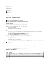
... to select a test based on (or restart) your Drivers and Utilities media. Starting the Dell Diagnostics From Your Hard Drive 1. Then shut down and restart the computer. Starting the Dell Diagnostics From the Drivers and Utilities Disc 1. Custom Test Tests a specific device. When the... boot sequence for your part. Back to Contents Page Diagnostics Dell™ OptiPlex™ 380 Service Manual-Desktop Dell Diagnostics Power Button Light Codes Beep Codes Diagnostic Lights Dell Diagnostics When to Use the Dell Diagnostics It is recommended that the device you want to test...
... to select a test based on (or restart) your Drivers and Utilities media. Starting the Dell Diagnostics From Your Hard Drive 1. Then shut down and restart the computer. Starting the Dell Diagnostics From the Drivers and Utilities Disc 1. Custom Test Tests a specific device. When the... boot sequence for your part. Back to Contents Page Diagnostics Dell™ OptiPlex™ 380 Service Manual-Desktop Dell Diagnostics Power Button Light Codes Beep Codes Diagnostic Lights Dell Diagnostics When to Use the Dell Diagnostics It is recommended that the device you want to test...
Service Manual
Page 13
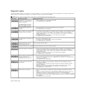
... memory modules (one at a time) until you have identified a faulty module or reinstalled all hard drive and optical drive cables are detected. l If available, install working memory of the same type into your computer. l If the problem persists, contact Dell. l If the operating system is correct for your computer. l If available, install working memory...
... memory modules (one at a time) until you have identified a faulty module or reinstalled all hard drive and optical drive cables are detected. l If available, install working memory of the same type into your computer. l If the problem persists, contact Dell. l If the operating system is correct for your computer. l If available, install working memory...
Service Manual
Page 16
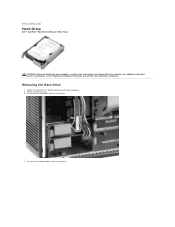
Back to Contents Page Hard Drive Dell™ OptiPlex™ 380 Service Manual-Mini-Tower WARNING: Before working inside your computer, read the safety information that shipped with your computer. Disconnect the data cable from the hard drive. Disconnect the power cable from the hard drive. 4. Remove the drive bezel. 3. Removing the Hard Drive 1. For additional safety best practices information, see the Regulatory Compliance Homepage at www.dell.com/regulatory_compliance. Follow the procedures in Before Working Inside Your Computer. 2.
Back to Contents Page Hard Drive Dell™ OptiPlex™ 380 Service Manual-Mini-Tower WARNING: Before working inside your computer, read the safety information that shipped with your computer. Disconnect the data cable from the hard drive. Disconnect the power cable from the hard drive. 4. Remove the drive bezel. 3. Removing the Hard Drive 1. For additional safety best practices information, see the Regulatory Compliance Homepage at www.dell.com/regulatory_compliance. Follow the procedures in Before Working Inside Your Computer. 2.

Service Manual
Page 17
Back to Contents Page Press in reverse order. Replacing the Hard Drive To replace the hard drive, perform the above steps in on the blue release tabs on each side of the hard drive and slide the hard drive out of the computer. 5.
Back to Contents Page Press in reverse order. Replacing the Hard Drive To replace the hard drive, perform the above steps in on the blue release tabs on each side of the hard drive and slide the hard drive out of the computer. 5.
Service Manual
Page 27
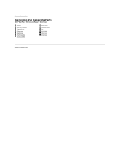
Back to Contents Page Removing and Replacing Parts Dell™ OptiPlex™ 380 Service Manual-Mini-Tower Cover Coin-Cell Battery Optical Drive Video Card Hard Drive Power Supply System Board Drive Bezel Memory Module Fan I/O Panel Heat Sink Processor Back to Contents Page
Back to Contents Page Removing and Replacing Parts Dell™ OptiPlex™ 380 Service Manual-Mini-Tower Cover Coin-Cell Battery Optical Drive Video Card Hard Drive Power Supply System Board Drive Bezel Memory Module Fan I/O Panel Heat Sink Processor Back to Contents Page
Service Manual
Page 30
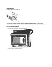
Removing the Power Supply 1. Disconnect the hard-drive power cable from the hard drive. For additional safety best practices information, see the Regulatory Compliance Homepage at www.dell.com/regulatory_compliance. Remove the screws that secure the power supply to Contents Page Power Supply Dell™ OptiPlex™ 380 Service Manual-Mini-Tower WARNING: Before working inside your computer, read the safety information that shipped with your computer. Back to the back of the computer. 3. Follow the procedures in Before Working Inside Your Computer. 2.
Removing the Power Supply 1. Disconnect the hard-drive power cable from the hard drive. For additional safety best practices information, see the Regulatory Compliance Homepage at www.dell.com/regulatory_compliance. Remove the screws that secure the power supply to Contents Page Power Supply Dell™ OptiPlex™ 380 Service Manual-Mini-Tower WARNING: Before working inside your computer, read the safety information that shipped with your computer. Back to the back of the computer. 3. Follow the procedures in Before Working Inside Your Computer. 2.


