Setup and Features Information Tech Sheet
Page 1
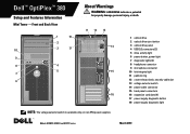
... 11 padlock ring 12 cover-release latch, security cable slot 13 voltage selector switch 14 power cable connector 15 back panel connectors 16 expansion card slots (4) 17 power supply diagnostic button 18 power supply diagnostic light NOTE: The voltage selector switch is available only on non-EPA power supplies. Dell™ OptiPlex™ 380 Setup and Features Information Mini Tower -
... 11 padlock ring 12 cover-release latch, security cable slot 13 voltage selector switch 14 power cable connector 15 back panel connectors 16 expansion card slots (4) 17 power supply diagnostic button 18 power supply diagnostic light NOTE: The voltage selector switch is available only on non-EPA power supplies. Dell™ OptiPlex™ 380 Setup and Features Information Mini Tower -
Setup and Features Information Tech Sheet
Page 2
... 15 NOTE: The voltage selector switch is available only on non-EPA power supplies. 1 optical drive 2 optical drive eject button 3 USB 2.0 connectors (2) 4 drive activity light 5 diagnostic lights (4) 6 power button, power light 7 link integrity light 8 microphone connector 9 headphone connector 10 power supply diagnostic button 11 power supply diagnostic light 12 voltage selector switch 13 cover-release latch, security cable...
... 15 NOTE: The voltage selector switch is available only on non-EPA power supplies. 1 optical drive 2 optical drive eject button 3 USB 2.0 connectors (2) 4 drive activity light 5 diagnostic lights (4) 6 power button, power light 7 link integrity light 8 microphone connector 9 headphone connector 10 power supply diagnostic button 11 power supply diagnostic light 12 voltage selector switch 13 cover-release latch, security cable...
Setup and Features Information Tech Sheet
Page 3
... 14 NOTE: The voltage selector switch is available only on non-EPA power supplies. 1 optical drive 2 optical drive eject button 3 USB 2.0 connectors (2) 4 power button, power light 5 link integrity light 6 diagnostic lights (4) 7 drive activity light 8 headphone connector 9 microphone connector 10 power supply diagnostic button 11 power supply diagnostic light 12 cover-release latch, security cable slot 13 padlock ring...
... 14 NOTE: The voltage selector switch is available only on non-EPA power supplies. 1 optical drive 2 optical drive eject button 3 USB 2.0 connectors (2) 4 power button, power light 5 link integrity light 6 diagnostic lights (4) 7 drive activity light 8 headphone connector 9 microphone connector 10 power supply diagnostic button 11 power supply diagnostic light 12 cover-release latch, security cable slot 13 padlock ring...
Setup and Features Information Tech Sheet
Page 7
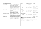
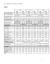
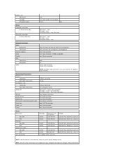
...light when the computer does not start indicates a problem with the system board. Green light - The computer is calculated by using the power supply wattage rating. Power Wattage Maximum heat dissipation Voltage Mini Tower: Non-EPA 255 W 1338 (BTU/hr) 115/230 VAC, 50/60 Hz, 6.5/3.5 A... - Blinking green light indicates that shipped with your computer for important voltage-setting information. Solid green light indicates power-on the Dell Support website at support.dell.com/manuals. Off (no light) - For information on the diagnostic lights, see the Service Manual available on...
...light when the computer does not start indicates a problem with the system board. Green light - The computer is calculated by using the power supply wattage rating. Power Wattage Maximum heat dissipation Voltage Mini Tower: Non-EPA 255 W 1338 (BTU/hr) 115/230 VAC, 50/60 Hz, 6.5/3.5 A... - Blinking green light indicates that shipped with your computer for important voltage-setting information. Solid green light indicates power-on the Dell Support website at support.dell.com/manuals. Off (no light) - For information on the diagnostic lights, see the Service Manual available on...
Guidebook
Page 3
... reducing risk and protecting your sensitive data with Dell's ProSupport Hard Drive Data Recovery and Certified Data Destruction services. with the Dell Client Energy Savings Calculator(www.dell.com/optiplex) Help reduce power consumption - Customizable to deliver cost-effective business productivity for multiple customized OptiPlex systems with Dell's power supply, which is up to a 12 month lifecycle (plus...
... reducing risk and protecting your sensitive data with Dell's ProSupport Hard Drive Data Recovery and Certified Data Destruction services. with the Dell Client Energy Savings Calculator(www.dell.com/optiplex) Help reduce power consumption - Customizable to deliver cost-effective business productivity for multiple customized OptiPlex systems with Dell's power supply, which is up to a 12 month lifecycle (plus...
Guidebook
Page 4
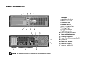
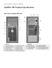
DELL™ OPTIPLEX™ 380 TECHNICAL GUIDEBOOK OptiPlex 380 Technical Specifications Mini Tower Computer (MT) View Front View 1 Optical Drive (optional) 6 Power Button, Power light 2 Optical Drive Eject Button 7 Diagnostic Lights (4) 3 Optical Drive Panel 8 Headphone Connector 4 USB 2.0 Connectors(2) 9 Microphone Connector 5 Hard ... 10 Network Connectivity Light Back View 11 Chassis Lock Loop 12 Cover Release Latch 13 Voltage Selector Switch 14 Power Connector 15 Back Panel Connectors 16 Expansion Card Slots (4) 17 Power Supply Diagnostic Button 18 Power Supply Diagnostic Light 4
DELL™ OPTIPLEX™ 380 TECHNICAL GUIDEBOOK OptiPlex 380 Technical Specifications Mini Tower Computer (MT) View Front View 1 Optical Drive (optional) 6 Power Button, Power light 2 Optical Drive Eject Button 7 Diagnostic Lights (4) 3 Optical Drive Panel 8 Headphone Connector 4 USB 2.0 Connectors(2) 9 Microphone Connector 5 Hard ... 10 Network Connectivity Light Back View 11 Chassis Lock Loop 12 Cover Release Latch 13 Voltage Selector Switch 14 Power Connector 15 Back Panel Connectors 16 Expansion Card Slots (4) 17 Power Supply Diagnostic Button 18 Power Supply Diagnostic Light 4
Guidebook
Page 5
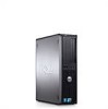
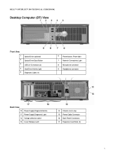
DELL™ OPTIPLEX™ 380 TECHNICAL GUIDEBOOK Desktop Computer (DT) View Front View 1 2 3 4 5 Optical Drive (optional) Optical Drive Eject Button USB 2.0 Connectors (2) Hard Drive Activity Light Diagnostic Lights (4) 6 Power button, Power light 7 Network Connectivity Light 8 Microphone connector 9 Headphone connector Back View 10 Power Supply Diagnostic Button 11 Power Supply Diagnostic Light 12 Voltage selection switch 13 Cover Release Latch 14 Chassis Lock Loop 15 Power Cable Connector 16 Back Panel Connectors 17 Expansion Card Slots (3) 5
DELL™ OPTIPLEX™ 380 TECHNICAL GUIDEBOOK Desktop Computer (DT) View Front View 1 2 3 4 5 Optical Drive (optional) Optical Drive Eject Button USB 2.0 Connectors (2) Hard Drive Activity Light Diagnostic Lights (4) 6 Power button, Power light 7 Network Connectivity Light 8 Microphone connector 9 Headphone connector Back View 10 Power Supply Diagnostic Button 11 Power Supply Diagnostic Light 12 Voltage selection switch 13 Cover Release Latch 14 Chassis Lock Loop 15 Power Cable Connector 16 Back Panel Connectors 17 Expansion Card Slots (3) 5
Guidebook
Page 6
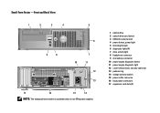
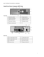
DELL™ OPTIPLEX™ 380 TECHNICAL GUIDEBOOK Small Form Factor Computer (SFF) View Front View 1 Optical Drive (optional) 2 Optical Drive Eject Button 3 USB 2.0 Connectors (2) 4 Power button, Power light 5 Network Connectivity Light 6 Diagnostic lights (4) 7 Hard Drive Activity Light 8 Headphone connector 9 Microphone connector Back View 10 Power Supply Diagnostic Button 11 Power Supply Diagnostic Light 12 Cover Release Latch 13 Chassis Lock Loop 14 Voltage Selection Switch 15 Power Cable Connector 16 Back Panel Connectors 17 Expansion Card Slots (3) 6
DELL™ OPTIPLEX™ 380 TECHNICAL GUIDEBOOK Small Form Factor Computer (SFF) View Front View 1 Optical Drive (optional) 2 Optical Drive Eject Button 3 USB 2.0 Connectors (2) 4 Power button, Power light 5 Network Connectivity Light 6 Diagnostic lights (4) 7 Hard Drive Activity Light 8 Headphone connector 9 Microphone connector Back View 10 Power Supply Diagnostic Button 11 Power Supply Diagnostic Light 12 Cover Release Latch 13 Chassis Lock Loop 14 Voltage Selection Switch 15 Power Cable Connector 16 Back Panel Connectors 17 Expansion Card Slots (3) 6
Guidebook
Page 19
... No Yes No Yes Yes Yes Yes Yes Yes Yes No Silver No Silver No Silver Yes Yes Yes Yes Yes Yes 19 DELL™ OPTIPLEX™ 380 TECHNICAL GUIDEBOOK Power Power Supply Wattage AC input Voltage Range AC input current (low ac range/high AC range) AC input Frequency AC holdup time (80%load) Average...
... No Yes No Yes Yes Yes Yes Yes Yes Yes No Silver No Silver No Silver Yes Yes Yes Yes Yes Yes 19 DELL™ OPTIPLEX™ 380 TECHNICAL GUIDEBOOK Power Power Supply Wattage AC input Voltage Range AC input current (low ac range/high AC range) AC input Frequency AC holdup time (80%load) Average...
Service Manual
Page 27
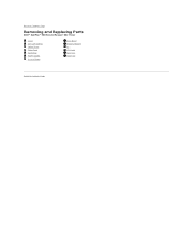
Back to Contents Page Removing and Replacing Parts Dell™ OptiPlex™ 380 Service Manual-Mini-Tower Cover Coin-Cell Battery Optical Drive Video Card Hard Drive Power Supply System Board Drive Bezel Memory Module Fan I/O Panel Heat Sink Processor Back to Contents Page
Back to Contents Page Removing and Replacing Parts Dell™ OptiPlex™ 380 Service Manual-Mini-Tower Cover Coin-Cell Battery Optical Drive Video Card Hard Drive Power Supply System Board Drive Bezel Memory Module Fan I/O Panel Heat Sink Processor Back to Contents Page
Service Manual
Page 30
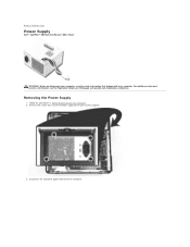
Removing the Power Supply 1. Disconnect the hard-drive power cable from the hard drive. Remove the screws that secure the power supply to Contents Page Power Supply Dell™ OptiPlex™ 380 Service Manual-Mini-Tower WARNING: Before working inside your computer, read the safety information that shipped with your computer. For additional safety best practices information, see the Regulatory Compliance Homepage at www.dell.com/regulatory_compliance. Back to the back of the computer. 3. Follow the procedures in Before Working Inside Your Computer. 2.
Removing the Power Supply 1. Disconnect the hard-drive power cable from the hard drive. Remove the screws that secure the power supply to Contents Page Power Supply Dell™ OptiPlex™ 380 Service Manual-Mini-Tower WARNING: Before working inside your computer, read the safety information that shipped with your computer. For additional safety best practices information, see the Regulatory Compliance Homepage at www.dell.com/regulatory_compliance. Back to the back of the computer. 3. Follow the procedures in Before Working Inside Your Computer. 2.

Service Manual
Page 32
Remove the I/O-panel data cable from the system board. 7. 6. Disconnect the main power cable from the cable routing clip at the base of the power supply.
Remove the I/O-panel data cable from the system board. 7. 6. Disconnect the main power cable from the cable routing clip at the base of the power supply.

Service Manual
Page 33
Press the release latch that secures the power supply to the chassis. Remove any data cables from the cable routing at the base of the power supply. 9. 8.
Press the release latch that secures the power supply to the chassis. Remove any data cables from the cable routing at the base of the power supply. 9. 8.

Service Manual
Page 34
Replacing the Power Supply To replace the power supply, perform the above steps in reverse order. Back to Contents Page 10. Slide the power supply towards the front of the computer and lift the power supply up and away from the computer.
Replacing the Power Supply To replace the power supply, perform the above steps in reverse order. Back to Contents Page 10. Slide the power supply towards the front of the computer and lift the power supply up and away from the computer.
Service Manual
Page 38
...cell 115/230 VAC, 50/60 Hz, 6.5/3.5 A 100-240 VAC, 50/60 Hz, 1.8/3.5 A NOTE: Heat dissipation is calculated by using the power supply wattage rating. System Board Connectors PCI 2.3: connectors data width (maximum) PCI Express x16: connectors data width (maximum) Serial ATA Memory Processor fan System... fan Front panel control/front panel audio Processor Power 12V Power 120-pin connector 32 bits 164-pin connector 16 PCI-Express lanes Mini-tower - two 7-pin connectors two 240-pin connectors one...
...cell 115/230 VAC, 50/60 Hz, 6.5/3.5 A 100-240 VAC, 50/60 Hz, 1.8/3.5 A NOTE: Heat dissipation is calculated by using the power supply wattage rating. System Board Connectors PCI 2.3: connectors data width (maximum) PCI Express x16: connectors data width (maximum) Serial ATA Memory Processor fan System... fan Front panel control/front panel audio Processor Power 12V Power 120-pin connector 32 bits 164-pin connector 16 PCI-Express lanes Mini-tower - two 7-pin connectors two 240-pin connectors one...


