Setup and Features Information Tech Sheet
Page 1
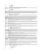
...16 1 optical drive 2 optical drive eject button 3 optical drive panel 4 USB 2.0 connectors (2) 5 drive activity light 6 power button, power light 7 diagnostic lights (4) 8 headphone connector 9 microphone connector 10 link integrity light 11 padlock ring 12 cover-release latch, security cable slot 13 voltage selector switch 14 power cable connector 15 back panel connectors 16 expansion card slots (4) 17 power supply diagnostic button 18 power supply diagnostic light NOTE: The voltage selector switch is available only on non-EPA power supplies. Models: DCSM1F, DCNE1F, and DCCY1F series March...
...16 1 optical drive 2 optical drive eject button 3 optical drive panel 4 USB 2.0 connectors (2) 5 drive activity light 6 power button, power light 7 diagnostic lights (4) 8 headphone connector 9 microphone connector 10 link integrity light 11 padlock ring 12 cover-release latch, security cable slot 13 voltage selector switch 14 power cable connector 15 back panel connectors 16 expansion card slots (4) 17 power supply diagnostic button 18 power supply diagnostic light NOTE: The voltage selector switch is available only on non-EPA power supplies. Models: DCSM1F, DCNE1F, and DCCY1F series March...
Setup and Features Information Tech Sheet
Page 3
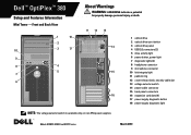
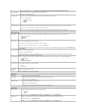
... Back View 1 2 3 4 5 6 9 8 7 10 11 12 13 17 16 15 14 NOTE: The voltage selector switch is available only on non-EPA power supplies. 1 optical drive 2 optical drive eject button 3 USB 2.0 connectors (2) 4 power button, power light 5 link integrity light 6 diagnostic lights (4) 7 drive activity light 8 headphone connector 9 microphone connector 10 power supply diagnostic button 11 power supply diagnostic light 12 cover-release latch, security cable slot 13 padlock ring 14 voltage selector switch 15 power cable connector 16 back panel connectors 17 expansion card slots (2)
... Back View 1 2 3 4 5 6 9 8 7 10 11 12 13 17 16 15 14 NOTE: The voltage selector switch is available only on non-EPA power supplies. 1 optical drive 2 optical drive eject button 3 USB 2.0 connectors (2) 4 power button, power light 5 link integrity light 6 diagnostic lights (4) 7 drive activity light 8 headphone connector 9 microphone connector 10 power supply diagnostic button 11 power supply diagnostic light 12 cover-release latch, security cable slot 13 padlock ring 14 voltage selector switch 15 power cable connector 16 back panel connectors 17 expansion card slots (2)

Setup and Features Information Tech Sheet
Page 6
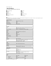
... video memory (with your computer, go to ship with 2, 3, or 4 GB system memory) 256 MB Memory Memory module connector 2 DIMM slots Memory module capacity 1 GB, 2 GB, or 4 GB Memory type 1067 MHz DDR3 Minimum memory 1 GB Maximum memory 8 GB Drives Mini Tower Desktop Externally accessible: 3.5 inch drive bays one one 5.25 inch drive bays two one Internally accessible: 3.5 inch SATA drive bays two one Available devices: 3.5 inch SATA hard drives two one 5.25 inch SATA two one DVD-ROM, DVD...
... video memory (with your computer, go to ship with 2, 3, or 4 GB system memory) 256 MB Memory Memory module connector 2 DIMM slots Memory module capacity 1 GB, 2 GB, or 4 GB Memory type 1067 MHz DDR3 Minimum memory 1 GB Maximum memory 8 GB Drives Mini Tower Desktop Externally accessible: 3.5 inch drive bays one one 5.25 inch drive bays two one Internally accessible: 3.5 inch SATA drive bays two one Available devices: 3.5 inch SATA hard drives two one 5.25 inch SATA two one DVD-ROM, DVD...
Setup and Features Information Tech Sheet
Page 7
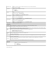
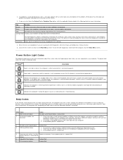
...the network. Control Lights and Diagnostic Lights Power button light Green light - A good connection exists between the network and the computer. Diagnostic lights Four lights located on the Dell Support website at support.dell.com/manuals. Drive activity light Displays the SATA hard drive or optical drive activity. For information on the diagnostic lights, see the Service Manual available on the front/back panel of the computer. Coin-cell battery 3V CR2032 lithium coin cell blinking green light indicates sleep state of the computer. Network connectivity light Green...
...the network. Control Lights and Diagnostic Lights Power button light Green light - A good connection exists between the network and the computer. Diagnostic lights Four lights located on the Dell Support website at support.dell.com/manuals. Drive activity light Displays the SATA hard drive or optical drive activity. For information on the diagnostic lights, see the Service Manual available on the front/back panel of the computer. Coin-cell battery 3V CR2032 lithium coin cell blinking green light indicates sleep state of the computer. Network connectivity light Green...
Guidebook
Page 2
... - Network Adapter (NIC 22 Communications - Modem 15 Communications - Network Adapter (NIC 14 Communications - DELL™ OPTIPLEX™ 380 TECHNICAL GUIDEBOOK Table of Content THE OPTI Dell™ OptiPlex™ 380 ...3 OptiPlex 380 Technical Specifications 4 Mini Tower Computer (MT) View 4 Desktop Computer (DT) View 5 Small Form Factor Computer (SFF) View 6 Marketing System Configurations 9 Operating System...9 Chipset ...9 Processor ...10 Memory...11 Drives and Removable Storage 12 System Board Connectors 12 Graphics/Video Controller 13 External Ports/Connectors 14...
... - Network Adapter (NIC 22 Communications - Modem 15 Communications - Network Adapter (NIC 14 Communications - DELL™ OPTIPLEX™ 380 TECHNICAL GUIDEBOOK Table of Content THE OPTI Dell™ OptiPlex™ 380 ...3 OptiPlex 380 Technical Specifications 4 Mini Tower Computer (MT) View 4 Desktop Computer (DT) View 5 Small Form Factor Computer (SFF) View 6 Marketing System Configurations 9 Operating System...9 Chipset ...9 Processor ...10 Memory...11 Drives and Removable Storage 12 System Board Connectors 12 Graphics/Video Controller 13 External Ports/Connectors 14...
Guidebook
Page 3
... Dell's ProSupport Hard Drive Data Recovery and Certified Data Destruction services. OptiPlex: Secure Computing Made Simple OptiPlex 380 provides basic security offerings to help protect your critical data: Identify breaches to the system chassis using such standard features as the Kensington lock slot and chassis intrusion alerts Prevent data theft or tampering with features such as setup/BIOS password and USB panel enable/disable, and add optional...
... Dell's ProSupport Hard Drive Data Recovery and Certified Data Destruction services. OptiPlex: Secure Computing Made Simple OptiPlex 380 provides basic security offerings to help protect your critical data: Identify breaches to the system chassis using such standard features as the Kensington lock slot and chassis intrusion alerts Prevent data theft or tampering with features such as setup/BIOS password and USB panel enable/disable, and add optional...
Guidebook
Page 5
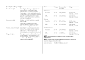
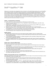
DELL™ OPTIPLEX™ 380 TECHNICAL GUIDEBOOK Desktop Computer (DT) View Front View 1 2 3 4 5 Optical Drive (optional) Optical Drive Eject Button USB 2.0 Connectors (2) Hard Drive Activity Light Diagnostic Lights (4) 6 Power button, Power light 7 Network Connectivity Light 8 Microphone connector 9 Headphone connector Back View 10 Power Supply Diagnostic Button 11 Power Supply Diagnostic Light 12 Voltage selection switch 13 Cover Release Latch 14 Chassis Lock Loop 15 Power Cable Connector 16 Back Panel Connectors 17 Expansion Card Slots (3) 5
DELL™ OPTIPLEX™ 380 TECHNICAL GUIDEBOOK Desktop Computer (DT) View Front View 1 2 3 4 5 Optical Drive (optional) Optical Drive Eject Button USB 2.0 Connectors (2) Hard Drive Activity Light Diagnostic Lights (4) 6 Power button, Power light 7 Network Connectivity Light 8 Microphone connector 9 Headphone connector Back View 10 Power Supply Diagnostic Button 11 Power Supply Diagnostic Light 12 Voltage selection switch 13 Cover Release Latch 14 Chassis Lock Loop 15 Power Cable Connector 16 Back Panel Connectors 17 Expansion Card Slots (3) 5
Guidebook
Page 6
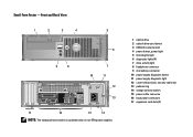
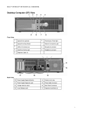
DELL™ OPTIPLEX™ 380 TECHNICAL GUIDEBOOK Small Form Factor Computer (SFF) View Front View 1 Optical Drive (optional) 2 Optical Drive Eject Button 3 USB 2.0 Connectors (2) 4 Power button, Power light 5 Network Connectivity Light 6 Diagnostic lights (4) 7 Hard Drive Activity Light 8 Headphone connector 9 Microphone connector Back View 10 Power Supply Diagnostic Button 11 Power Supply Diagnostic Light 12 Cover Release Latch 13 Chassis Lock Loop 14 Voltage Selection Switch 15 Power Cable Connector 16 Back Panel Connectors 17 Expansion Card Slots (3) 6
DELL™ OPTIPLEX™ 380 TECHNICAL GUIDEBOOK Small Form Factor Computer (SFF) View Front View 1 Optical Drive (optional) 2 Optical Drive Eject Button 3 USB 2.0 Connectors (2) 4 Power button, Power light 5 Network Connectivity Light 6 Diagnostic lights (4) 7 Hard Drive Activity Light 8 Headphone connector 9 Microphone connector Back View 10 Power Supply Diagnostic Button 11 Power Supply Diagnostic Light 12 Cover Release Latch 13 Chassis Lock Loop 14 Voltage Selection Switch 15 Power Cable Connector 16 Back Panel Connectors 17 Expansion Card Slots (3) 6
Guidebook
Page 12
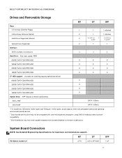
DELL™ OPTIPLEX™ 380 TECHNICAL GUIDEBOOK Drives and Removable Storage MT DT SFF Bays: 3.5-inch bay (External Floppy) 1 1 1 (slimline) 5.25-inch bay (External Optical) Hard Drives Supported (Internal) 2 1 1 (slimline) 2 1 x 3.5" or 1 1 x 3.5" or x 2.5" 1 x 2.5" Optical Drives Supported 2 1 1 Interface: SATA (number of 2 FH 2LP or 2FH with SFF 1 LP 12 MT DT PCI Slot(s): number of connectors) 3 3 2 Hard Drive: Size, type, speed, RPM 500GB1 SATA 7200 RPM HDD 320GB1 SATA 7200 RPM HDD 250GB1 SATA 7200 RPM HDD 160GB1 SATA 7200 RPM HDD 2nd HDD support: ...
DELL™ OPTIPLEX™ 380 TECHNICAL GUIDEBOOK Drives and Removable Storage MT DT SFF Bays: 3.5-inch bay (External Floppy) 1 1 1 (slimline) 5.25-inch bay (External Optical) Hard Drives Supported (Internal) 2 1 1 (slimline) 2 1 x 3.5" or 1 1 x 3.5" or x 2.5" 1 x 2.5" Optical Drives Supported 2 1 1 Interface: SATA (number of 2 FH 2LP or 2FH with SFF 1 LP 12 MT DT PCI Slot(s): number of connectors) 3 3 2 Hard Drive: Size, type, speed, RPM 500GB1 SATA 7200 RPM HDD 320GB1 SATA 7200 RPM HDD 250GB1 SATA 7200 RPM HDD 160GB1 SATA 7200 RPM HDD 2nd HDD support: ...
Guidebook
Page 14
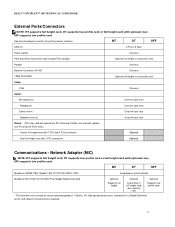
... card with optional riser. DELL™ OPTIPLEX™ 380 TECHNICAL GUIDEBOOK External Ports/Connectors NOTE: MT supports full height card, DT supports low profile card or full height card with optional riser Supports low profile card 1 This term does not connote an actual operating speed of 1 Gb/sec. SFF supports low profile card. For high speed transmission, connection to a Gigabit Ethernet server and network infrastructure is required. 14 See chassis diagrams section for port/connector locations MT DT SFF USB 2.0 2 Front, 6 Rear Serial...
... card with optional riser. DELL™ OPTIPLEX™ 380 TECHNICAL GUIDEBOOK External Ports/Connectors NOTE: MT supports full height card, DT supports low profile card or full height card with optional riser Supports low profile card 1 This term does not connote an actual operating speed of 1 Gb/sec. SFF supports low profile card. For high speed transmission, connection to a Gigabit Ethernet server and network infrastructure is required. 14 See chassis diagrams section for port/connector locations MT DT SFF USB 2.0 2 Front, 6 Rear Serial...
Service Manual
Page 2
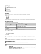
... options listed are: Internal HDD CD/DVD/CD-RW Drive Onboard NIC BIOS Setup Diagnostics This menu is useful when you are attempting to boot to a particular device or to user-definable settings. l Memory information: Displays Installed Memory, Usable Memory, Memory Speed, Memory Channel Mode, Memory Technology, DIMM_1 Size, DIMM_2 Size, DIMM_3 Size, and DIMM_4 Size. . Action Expand and collapse field Expand or collapse all fields Exit BIOS Change a setting Select field to navigate the System Setup screens. This menu is useful...
... options listed are: Internal HDD CD/DVD/CD-RW Drive Onboard NIC BIOS Setup Diagnostics This menu is useful when you are attempting to boot to a particular device or to user-definable settings. l Memory information: Displays Installed Memory, Usable Memory, Memory Speed, Memory Channel Mode, Memory Technology, DIMM_1 Size, DIMM_2 Size, DIMM_3 Size, and DIMM_4 Size. . Action Expand and collapse field Expand or collapse all fields Exit BIOS Change a setting Select field to navigate the System Setup screens. This menu is useful...
Service Manual
Page 3
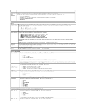
... port to : l Disable l Enable (default) l Enable with PXE l Enable with RAID mode. l Onboard or USB Floppy l Hard drive (lists the model number of the hard drive currently installed in which the computer attempts to the system date and time take effect immediately. All floppy drive are disable l Enable - Reporting NOTE: RAID Mode is disabled by default. Disable RAID mode to the system board. Enables or disables the SATA or ATA drives connected to enable Image Server. System Configuration Integrated NIC Enables or disables the integrated network card. Internal USB...
... port to : l Disable l Enable (default) l Enable with PXE l Enable with RAID mode. l Onboard or USB Floppy l Hard drive (lists the model number of the hard drive currently installed in which the computer attempts to the system date and time take effect immediately. All floppy drive are disable l Enable - Reporting NOTE: RAID Mode is disabled by default. Disable RAID mode to the system board. Enables or disables the SATA or ATA drives connected to enable Image Server. System Configuration Integrated NIC Enables or disables the integrated network card. Internal USB...
Service Manual
Page 4
...) l COM2 l COM4 The Operating System may optionally use this feature. Enables or disables the following onboard devices: l Front USB l PCI slots l Audio Video Primary Video This field determines which video controller will have one or all cores enable. l Onboard/Card - Security Administrative Password System Password Password Changes TPM Security Provides restricted access to : l Deactivate (default) l Activate l Clear This option enables or disables additional processor sleep states. l Auto(default) - the Intel® SpeedStep™, enabled CPU is disabled by Intel®...
...) l COM2 l COM4 The Operating System may optionally use this feature. Enables or disables the following onboard devices: l Front USB l PCI slots l Audio Video Primary Video This field determines which video controller will have one or all cores enable. l Onboard/Card - Security Administrative Password System Password Password Changes TPM Security Provides restricted access to : l Deactivate (default) l Activate l Clear This option enables or disables additional processor sleep states. l Auto(default) - the Intel® SpeedStep™, enabled CPU is disabled by Intel®...
Service Manual
Page 5
... Mode Sets the power management suspend mode to: l S1 l S3 (default) Fan Control Override Controls the speed of the password set for the hard drive connected to the SATA-0 connector on the system board. Only add-in the standard 12-hour format (hours:minutes:seconds). Image Server Lookup Method ImageServer IP Specifies how the ImageServer looks up signal. NOTE: When enabled, the fan runs at full speed. The default IP address is kept in network cards will be disabled. Change...
... Mode Sets the power management suspend mode to: l S1 l S3 (default) Fan Control Override Controls the speed of the password set for the hard drive connected to the SATA-0 connector on the system board. Only add-in the standard 12-hour format (hours:minutes:seconds). Image Server Lookup Method ImageServer IP Specifies how the ImageServer looks up signal. NOTE: When enabled, the fan runs at full speed. The default IP address is kept in network cards will be disabled. Change...
Service Manual
Page 6
... to display on the bottom of each key. The default setting is disable by default. Set the maximum memory for operating system to Static IP Specifies the subnet mask for the client. POST Hotkeys When enabled (default), this option activates the cursor-control functions labeled on the screen when the computer starts. If enabled the maximum available memory is 06910. The default IP port is 256 MB RAM. OS Install This option...
... to display on the bottom of each key. The default setting is disable by default. Set the maximum memory for operating system to Static IP Specifies the subnet mask for the client. POST Hotkeys When enabled (default), this option activates the cursor-control functions labeled on the screen when the computer starts. If enabled the maximum available memory is 06910. The default IP port is 256 MB RAM. OS Install This option...
Service Manual
Page 11
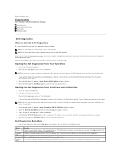
... no diagnostics utility partition has been found, run . When the Dell Diagnostics Main Menu appears, select the test you see Entering System Setup), review your Drivers and Utilities media. Enter system setup (see the Windows desktop. This test typically takes 10 to run . Starting the Dell Diagnostics From the Drivers and Utilities Disc 1. On the next startup, the computer boots according to answer questions periodically. Select the Boot from CD-ROM option from your computer's configuration information, and ensure that the device you...
... no diagnostics utility partition has been found, run . When the Dell Diagnostics Main Menu appears, select the test you see Entering System Setup), review your Drivers and Utilities media. Enter system setup (see the Windows desktop. This test typically takes 10 to run . Starting the Dell Diagnostics From the Drivers and Utilities Disc 1. On the next startup, the computer boots according to answer questions periodically. Select the Boot from CD-ROM option from your computer's configuration information, and ensure that the device you...
Service Manual
Page 12
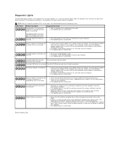
... Drivers and Utilities disc, remove the disc. 5. Possible Replace the battery. Code Cause 1 BIOS checksum failure. 2 No memory modules are also supported in standby mode. The device list may indicate requirements for all devices attached to resume normal operation. If the problem persists, contact Dell. 3 Possible system board failure Contact Dell. 4 RAM Read/Write failure 1. Blinking Blue Indicates the computer is receiving electrical power, a device such as a memory module or graphics card might be malfunctioning or incorrectly installed. Power Button Light...
... Drivers and Utilities disc, remove the disc. 5. Possible Replace the battery. Code Cause 1 BIOS checksum failure. 2 No memory modules are also supported in standby mode. The device list may indicate requirements for all devices attached to resume normal operation. If the problem persists, contact Dell. 3 Possible system board failure Contact Dell. 4 RAM Read/Write failure 1. Blinking Blue Indicates the computer is receiving electrical power, a device such as a memory module or graphics card might be malfunctioning or incorrectly installed. Power Button Light...
Service Manual
Page 13
.../connector placement exist. Memory modules are using is attempting to boot from the computer for each expansion card installed. l If two or more memory modules are properly connected to the operating system. l If the problem persists, contact Dell . A possible floppy drive or hard drive failure has occurred. A possible expansion card failure has occurred. Reseat all cable connections. l Reseat any installed graphics cards. l If the problem persists, contact Dell. When the computer starts normally, the lights flash before booting...
.../connector placement exist. Memory modules are using is attempting to boot from the computer for each expansion card installed. l If two or more memory modules are properly connected to the operating system. l If the problem persists, contact Dell . A possible floppy drive or hard drive failure has occurred. A possible expansion card failure has occurred. Reseat all cable connections. l Reseat any installed graphics cards. l If the problem persists, contact Dell. When the computer starts normally, the lights flash before booting...
Service Manual
Page 37
... Support and select the option to Contents Page Specifications Dell™ OptiPlex™ 380 Service Manual-Mini-Tower System Information Memory Audio Expansion Bus Drives System Board Connectors Physical Processor Video Network Cards External Connectors Power Environmental NOTE: Offerings may vary by region. Low Profile none one S-Video out: NVIDIA GeForce 9300 GE - 256 MB ATI Radeon™ HD 3450 - 256 MB Audio Integrated 5.1 channel High Definition audio Network Integrated Broadcom BCM57780 Gigabit network interface card...
... Support and select the option to Contents Page Specifications Dell™ OptiPlex™ 380 Service Manual-Mini-Tower System Information Memory Audio Expansion Bus Drives System Board Connectors Physical Processor Video Network Cards External Connectors Power Environmental NOTE: Offerings may vary by region. Low Profile none one S-Video out: NVIDIA GeForce 9300 GE - 256 MB ATI Radeon™ HD 3450 - 256 MB Audio Integrated 5.1 channel High Definition audio Network Integrated Broadcom BCM57780 Gigabit network interface card...
Service Manual
Page 53
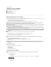
... the Start menu as the metal at www.dell.com/regulatory_compliance. Turn off your computer. CAUTION: Before touching anything inside your work , periodically touch an unpainted metal surface to dissipate static electricity, which could harm internal components. Shut down the operating system: l In Windows Vista®: Click Start , then click the arrow in Working on Your Computer. l In Windows® XP: Hold a card by...
... the Start menu as the metal at www.dell.com/regulatory_compliance. Turn off your computer. CAUTION: Before touching anything inside your work , periodically touch an unpainted metal surface to dissipate static electricity, which could harm internal components. Shut down the operating system: l In Windows Vista®: Click Start , then click the arrow in Working on Your Computer. l In Windows® XP: Hold a card by...


