Setup and Features Information Tech Sheet
Page 1
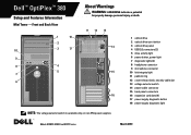
Dell™ OptiPlex™ 380 Setup and Features Information Mini Tower - Front and Back View 1 18 2 10 3 17 9 8 4 5 7 6 About Warnings WARNING: A WARNING indicates a potential for property damage, personal injury, or death. 11 12 13 14 15 16 1 optical drive 2 optical drive eject button 3 optical drive panel 4 USB 2.0 connectors (2) 5 drive activity light 6 power button, power... slot 13 voltage selector switch 14 power cable connector 15 back panel connectors 16 expansion card slots (4) 17 power supply diagnostic button 18 power supply diagnostic light NOTE: The voltage selector...
Dell™ OptiPlex™ 380 Setup and Features Information Mini Tower - Front and Back View 1 18 2 10 3 17 9 8 4 5 7 6 About Warnings WARNING: A WARNING indicates a potential for property damage, personal injury, or death. 11 12 13 14 15 16 1 optical drive 2 optical drive eject button 3 optical drive panel 4 USB 2.0 connectors (2) 5 drive activity light 6 power button, power... slot 13 voltage selector switch 14 power cable connector 15 back panel connectors 16 expansion card slots (4) 17 power supply diagnostic button 18 power supply diagnostic light NOTE: The voltage selector...
Setup and Features Information Tech Sheet
Page 2
... 15 NOTE: The voltage selector switch is available only on non-EPA power supplies. 1 optical drive 2 optical drive eject button 3 USB 2.0 connectors (2) 4 drive activity light 5 diagnostic lights (4) 6 power button, power light 7 link integrity light 8 microphone connector 9 headphone connector 10 power supply diagnostic button 11 power supply diagnostic light 12 voltage selector switch 13 cover-release latch, security cable...
... 15 NOTE: The voltage selector switch is available only on non-EPA power supplies. 1 optical drive 2 optical drive eject button 3 USB 2.0 connectors (2) 4 drive activity light 5 diagnostic lights (4) 6 power button, power light 7 link integrity light 8 microphone connector 9 headphone connector 10 power supply diagnostic button 11 power supply diagnostic light 12 voltage selector switch 13 cover-release latch, security cable...
Setup and Features Information Tech Sheet
Page 3
... 14 NOTE: The voltage selector switch is available only on non-EPA power supplies. 1 optical drive 2 optical drive eject button 3 USB 2.0 connectors (2) 4 power button, power light 5 link integrity light 6 diagnostic lights (4) 7 drive activity light 8 headphone connector 9 microphone connector 10 power supply diagnostic button 11 power supply diagnostic light 12 cover-release latch, security cable slot 13 padlock ring...
... 14 NOTE: The voltage selector switch is available only on non-EPA power supplies. 1 optical drive 2 optical drive eject button 3 USB 2.0 connectors (2) 4 power button, power light 5 link integrity light 6 diagnostic lights (4) 7 drive activity light 8 headphone connector 9 microphone connector 10 power supply diagnostic button 11 power supply diagnostic light 12 cover-release latch, security cable slot 13 padlock ring...
Setup and Features Information Tech Sheet
Page 7
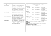
.... The computer is calculated by using the power supply wattage rating. Drive activity light Displays the SATA hard drive or optical drive activity. Power Wattage Maximum heat dissipation Voltage Mini Tower: ... lithium coin cell Blinking amber light indicates a problem with the system board or power supply. Diagnostic lights Four lights located on state; Amber light - Blinking green light ...between the network and the computer. Off (no light) - Solid green light indicates power-on the front/back panel of the computer. Network connectivity light Green light - For...
.... The computer is calculated by using the power supply wattage rating. Drive activity light Displays the SATA hard drive or optical drive activity. Power Wattage Maximum heat dissipation Voltage Mini Tower: ... lithium coin cell Blinking amber light indicates a problem with the system board or power supply. Diagnostic lights Four lights located on state; Amber light - Blinking green light ...between the network and the computer. Off (no light) - Solid green light indicates power-on the front/back panel of the computer. Network connectivity light Green light - For...
Guidebook
Page 3
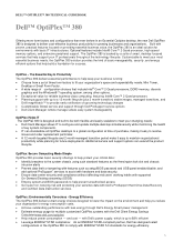
... running: Choose from a set of configuration choices that help prevent unauthorized access Get suport on providing essential business value, the OptiPlex 380 is an ideal solution for environments with ENERGY STAR 5.0 standards for success. with Dell's power supply, which is up to a 12 month lifecycle (plus 2 month transition) stable images, managed transitions, and...
... running: Choose from a set of configuration choices that help prevent unauthorized access Get suport on providing essential business value, the OptiPlex 380 is an ideal solution for environments with ENERGY STAR 5.0 standards for success. with Dell's power supply, which is up to a 12 month lifecycle (plus 2 month transition) stable images, managed transitions, and...
Guidebook
Page 4
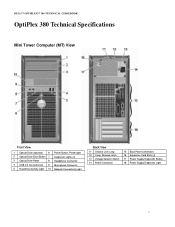
DELL™ OPTIPLEX™ 380 TECHNICAL GUIDEBOOK OptiPlex 380 Technical Specifications Mini Tower Computer (MT) View Front View 1 Optical Drive (optional) 6 Power Button, Power light 2 Optical Drive Eject Button 7 Diagnostic Lights (4) 3 Optical Drive Panel 8 Headphone Connector 4 USB 2.0 Connectors(2) 9 Microphone Connector 5 Hard ... 10 Network Connectivity Light Back View 11 Chassis Lock Loop 12 Cover Release Latch 13 Voltage Selector Switch 14 Power Connector 15 Back Panel Connectors 16 Expansion Card Slots (4) 17 Power Supply Diagnostic Button 18 Power Supply Diagnostic Light 4
DELL™ OPTIPLEX™ 380 TECHNICAL GUIDEBOOK OptiPlex 380 Technical Specifications Mini Tower Computer (MT) View Front View 1 Optical Drive (optional) 6 Power Button, Power light 2 Optical Drive Eject Button 7 Diagnostic Lights (4) 3 Optical Drive Panel 8 Headphone Connector 4 USB 2.0 Connectors(2) 9 Microphone Connector 5 Hard ... 10 Network Connectivity Light Back View 11 Chassis Lock Loop 12 Cover Release Latch 13 Voltage Selector Switch 14 Power Connector 15 Back Panel Connectors 16 Expansion Card Slots (4) 17 Power Supply Diagnostic Button 18 Power Supply Diagnostic Light 4
Guidebook
Page 5
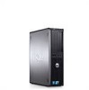
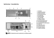
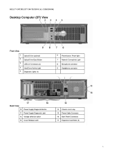
DELL™ OPTIPLEX™ 380 TECHNICAL GUIDEBOOK Desktop Computer (DT) View Front View 1 2 3 4 5 Optical Drive (optional) Optical Drive Eject Button USB 2.0 Connectors (2) Hard Drive Activity Light Diagnostic Lights (4) 6 Power button, Power light 7 Network Connectivity Light 8 Microphone connector 9 Headphone connector Back View 10 Power Supply Diagnostic Button 11 Power Supply Diagnostic Light 12 Voltage selection switch 13 Cover Release Latch 14 Chassis Lock Loop 15 Power Cable Connector 16 Back Panel Connectors 17 Expansion Card Slots (3) 5
DELL™ OPTIPLEX™ 380 TECHNICAL GUIDEBOOK Desktop Computer (DT) View Front View 1 2 3 4 5 Optical Drive (optional) Optical Drive Eject Button USB 2.0 Connectors (2) Hard Drive Activity Light Diagnostic Lights (4) 6 Power button, Power light 7 Network Connectivity Light 8 Microphone connector 9 Headphone connector Back View 10 Power Supply Diagnostic Button 11 Power Supply Diagnostic Light 12 Voltage selection switch 13 Cover Release Latch 14 Chassis Lock Loop 15 Power Cable Connector 16 Back Panel Connectors 17 Expansion Card Slots (3) 5
Guidebook
Page 6
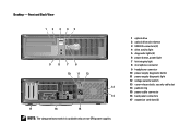
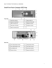
DELL™ OPTIPLEX™ 380 TECHNICAL GUIDEBOOK Small Form Factor Computer (SFF) View Front View 1 Optical Drive (optional) 2 Optical Drive Eject Button 3 USB 2.0 Connectors (2) 4 Power button, Power light 5 Network Connectivity Light 6 Diagnostic lights (4) 7 Hard Drive Activity Light 8 Headphone connector 9 Microphone connector Back View 10 Power Supply Diagnostic Button 11 Power Supply Diagnostic Light 12 Cover Release Latch 13 Chassis Lock Loop 14 Voltage Selection Switch 15 Power Cable Connector 16 Back Panel Connectors 17 Expansion Card Slots (3) 6
DELL™ OPTIPLEX™ 380 TECHNICAL GUIDEBOOK Small Form Factor Computer (SFF) View Front View 1 Optical Drive (optional) 2 Optical Drive Eject Button 3 USB 2.0 Connectors (2) 4 Power button, Power light 5 Network Connectivity Light 6 Diagnostic lights (4) 7 Hard Drive Activity Light 8 Headphone connector 9 Microphone connector Back View 10 Power Supply Diagnostic Button 11 Power Supply Diagnostic Light 12 Cover Release Latch 13 Chassis Lock Loop 14 Voltage Selection Switch 15 Power Cable Connector 16 Back Panel Connectors 17 Expansion Card Slots (3) 6
Guidebook
Page 19
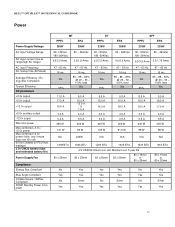
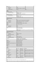
DELL™ OPTIPLEX™ 380 TECHNICAL GUIDEBOOK Power Power Supply Wattage AC input Voltage Range AC input current (low ac range/high AC range) AC input Frequency AC holdup time (80%load) Average Efficiency ( Energy Star Compliant) Typical Efficiency DC parameters +3.3v output +5.0v output +12.0v output +5.0v auxiliary output -12.0v output Max total power... 3.3v CMOS battery (type and estimated battery life) Power Supply Fan Compliance: Energy Star Compliant Blue Angel Compliant Climate Savers / 80Plus Compliant FEMP Standby Power Compliant MT PPFC EPA 255W 255W 90~135Vac, 180~264Vac...
DELL™ OPTIPLEX™ 380 TECHNICAL GUIDEBOOK Power Power Supply Wattage AC input Voltage Range AC input current (low ac range/high AC range) AC input Frequency AC holdup time (80%load) Average Efficiency ( Energy Star Compliant) Typical Efficiency DC parameters +3.3v output +5.0v output +12.0v output +5.0v auxiliary output -12.0v output Max total power... 3.3v CMOS battery (type and estimated battery life) Power Supply Fan Compliance: Energy Star Compliant Blue Angel Compliant Climate Savers / 80Plus Compliant FEMP Standby Power Compliant MT PPFC EPA 255W 255W 90~135Vac, 180~264Vac...
Service Manual
Page 27
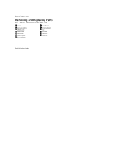
Back to Contents Page Removing and Replacing Parts Dell™ OptiPlex™ 380 Service Manual-Mini-Tower Cover Coin-Cell Battery Optical Drive Video Card Hard Drive Power Supply System Board Drive Bezel Memory Module Fan I/O Panel Heat Sink Processor Back to Contents Page
Back to Contents Page Removing and Replacing Parts Dell™ OptiPlex™ 380 Service Manual-Mini-Tower Cover Coin-Cell Battery Optical Drive Video Card Hard Drive Power Supply System Board Drive Bezel Memory Module Fan I/O Panel Heat Sink Processor Back to Contents Page
Service Manual
Page 30
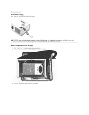
Remove the screws that secure the power supply to Contents Page Power Supply Dell™ OptiPlex™ 380 Service Manual-Mini-Tower WARNING: Before working inside your computer, read the safety information that shipped with your computer. For additional safety best practices information, see the Regulatory Compliance Homepage at www.dell.com/regulatory_compliance. Removing the Power Supply 1. Follow the procedures in Before Working Inside Your Computer. 2. Back to the back of the computer. 3. Disconnect the hard-drive power cable from the hard drive.
Remove the screws that secure the power supply to Contents Page Power Supply Dell™ OptiPlex™ 380 Service Manual-Mini-Tower WARNING: Before working inside your computer, read the safety information that shipped with your computer. For additional safety best practices information, see the Regulatory Compliance Homepage at www.dell.com/regulatory_compliance. Removing the Power Supply 1. Follow the procedures in Before Working Inside Your Computer. 2. Back to the back of the computer. 3. Disconnect the hard-drive power cable from the hard drive.

Service Manual
Page 32
6. Remove the I/O-panel data cable from the system board. 7. Disconnect the main power cable from the cable routing clip at the base of the power supply.
6. Remove the I/O-panel data cable from the system board. 7. Disconnect the main power cable from the cable routing clip at the base of the power supply.

Service Manual
Page 33
Press the release latch that secures the power supply to the chassis. Remove any data cables from the cable routing at the base of the power supply. 9. 8.
Press the release latch that secures the power supply to the chassis. Remove any data cables from the cable routing at the base of the power supply. 9. 8.

Service Manual
Page 34
Slide the power supply towards the front of the computer and lift the power supply up and away from the computer. Back to Contents Page Replacing the Power Supply To replace the power supply, perform the above steps in reverse order. 10.
Slide the power supply towards the front of the computer and lift the power supply up and away from the computer. Back to Contents Page Replacing the Power Supply To replace the power supply, perform the above steps in reverse order. 10.
Service Manual
Page 38
...x16: connectors data width (maximum) Serial ATA Memory Processor fan System fan Front panel control/front panel audio Processor Power 12V Power 120-pin connector 32 bits 164-pin connector 16 PCI-Express lanes Mini-tower - NOTE: See the safety ...5-pin connector one 40-pin connector one LGA775 connector one 4-pin connector one Small form factor - one 24-pin connector Power Mini-Tower: Non-EPA EPA Desktop: Non-EPA EPA Small Form Factor: Non-EPA EPA Coin-cell battery Wattage 255... A 100-240 VAC, 50/60 Hz, 1.8/3.5 A NOTE: Heat dissipation is calculated by using the power supply wattage rating.
...x16: connectors data width (maximum) Serial ATA Memory Processor fan System fan Front panel control/front panel audio Processor Power 12V Power 120-pin connector 32 bits 164-pin connector 16 PCI-Express lanes Mini-tower - NOTE: See the safety ...5-pin connector one 40-pin connector one LGA775 connector one 4-pin connector one Small form factor - one 24-pin connector Power Mini-Tower: Non-EPA EPA Desktop: Non-EPA EPA Small Form Factor: Non-EPA EPA Coin-cell battery Wattage 255... A 100-240 VAC, 50/60 Hz, 1.8/3.5 A NOTE: Heat dissipation is calculated by using the power supply wattage rating.


