Setup and Features Information Tech Sheet
Page 1
...2 optical drive eject button 3 optical drive panel 4 USB 2.0 connectors (2) 5 drive activity light 6 power button, power light 7 diagnostic lights (4) 8 headphone connector 9 microphone connector 10 link integrity light 11 padlock ring 12 cover-release latch, security cable slot 13 voltage selector switch 14 power ...expansion card slots (4) 17 power supply diagnostic button 18 power supply diagnostic light NOTE: The voltage selector switch is available only on non-EPA power supplies. Dell™ OptiPlex™ 380 Setup and Features Information Mini Tower - Models: DCSM1F, DCNE1F, and ...
...2 optical drive eject button 3 optical drive panel 4 USB 2.0 connectors (2) 5 drive activity light 6 power button, power light 7 diagnostic lights (4) 8 headphone connector 9 microphone connector 10 link integrity light 11 padlock ring 12 cover-release latch, security cable slot 13 voltage selector switch 14 power ...expansion card slots (4) 17 power supply diagnostic button 18 power supply diagnostic light NOTE: The voltage selector switch is available only on non-EPA power supplies. Dell™ OptiPlex™ 380 Setup and Features Information Mini Tower - Models: DCSM1F, DCNE1F, and ...
Setup and Features Information Tech Sheet
Page 2
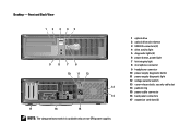
... on non-EPA power supplies. 1 optical drive 2 optical drive eject button 3 USB 2.0 connectors (2) 4 drive activity light 5 diagnostic lights (4) 6 power button, power light 7 link integrity light 8 microphone connector 9 headphone connector 10 power supply diagnostic button 11 power supply diagnostic light 12 voltage selector switch 13 cover-release latch, security cable slot 14 padlock ring 15 power...
... on non-EPA power supplies. 1 optical drive 2 optical drive eject button 3 USB 2.0 connectors (2) 4 drive activity light 5 diagnostic lights (4) 6 power button, power light 7 link integrity light 8 microphone connector 9 headphone connector 10 power supply diagnostic button 11 power supply diagnostic light 12 voltage selector switch 13 cover-release latch, security cable slot 14 padlock ring 15 power...
Setup and Features Information Tech Sheet
Page 3
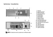
... on non-EPA power supplies. 1 optical drive 2 optical drive eject button 3 USB 2.0 connectors (2) 4 power button, power light 5 link integrity light 6 diagnostic lights (4) 7 drive activity light 8 headphone connector 9 microphone connector 10 power supply diagnostic button 11 power supply diagnostic light 12 cover-release latch, security cable slot 13 padlock ring 14 voltage selector switch 15 power...
... on non-EPA power supplies. 1 optical drive 2 optical drive eject button 3 USB 2.0 connectors (2) 4 power button, power light 5 link integrity light 6 diagnostic lights (4) 7 drive activity light 8 headphone connector 9 microphone connector 10 power supply diagnostic button 11 power supply diagnostic light 12 cover-release latch, security cable slot 13 padlock ring 14 voltage selector switch 15 power...
Setup and Features Information Tech Sheet
Page 4
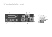
Back Panel 1 9 8 2 3 4 7 1 parallel connector 2 link integrity light 5 3 network adapter connector 4 network activity light 5 line-out connector 6 line-in/microphone connector 7 USB 2.0 connectors (6) 6 8 VGA connector 9 serial connector Mini Tower, Desktop, and Small Form Factor -
Back Panel 1 9 8 2 3 4 7 1 parallel connector 2 link integrity light 5 3 network adapter connector 4 network activity light 5 line-out connector 6 line-in/microphone connector 7 USB 2.0 connectors (6) 6 8 VGA connector 9 serial connector Mini Tower, Desktop, and Small Form Factor -
Setup and Features Information Tech Sheet
Page 7
...; Coin-cell battery 3V CR2032 lithium coin cell Solid amber light when the computer does not start indicates a problem with the system board. Off (no light) - Control Lights and Diagnostic Lights Power button light Green light - blinking green light indicates sleep state of the computer. Power Wattage Maximum heat ... (BTU/hr) 100-240 VAC, 50/60 Hz, 1.75/3.5 A NOTE: Heat dissipation is not detecting a physical connection to the drive. Green light - For information on the diagnostic lights, see the Service Manual available on the Dell Support website at support...
...; Coin-cell battery 3V CR2032 lithium coin cell Solid amber light when the computer does not start indicates a problem with the system board. Off (no light) - Control Lights and Diagnostic Lights Power button light Green light - blinking green light indicates sleep state of the computer. Power Wattage Maximum heat ... (BTU/hr) 100-240 VAC, 50/60 Hz, 1.75/3.5 A NOTE: Heat dissipation is not detecting a physical connection to the drive. Green light - For information on the diagnostic lights, see the Service Manual available on the Dell Support website at support...
Guidebook
Page 4
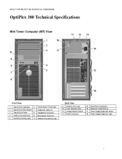
DELL™ OPTIPLEX™ 380 TECHNICAL GUIDEBOOK OptiPlex 380 Technical Specifications Mini Tower Computer (MT) View Front View 1 Optical Drive (optional) 6 Power Button, Power light 2 Optical Drive Eject Button 7 Diagnostic Lights (4) 3 Optical Drive Panel 8 Headphone Connector 4 USB 2.0 Connectors(2) 9 Microphone Connector 5 Hard Drive Activity Light 10 Network Connectivity Light Back View 11 Chassis Lock Loop 12 Cover Release Latch 13 Voltage...
DELL™ OPTIPLEX™ 380 TECHNICAL GUIDEBOOK OptiPlex 380 Technical Specifications Mini Tower Computer (MT) View Front View 1 Optical Drive (optional) 6 Power Button, Power light 2 Optical Drive Eject Button 7 Diagnostic Lights (4) 3 Optical Drive Panel 8 Headphone Connector 4 USB 2.0 Connectors(2) 9 Microphone Connector 5 Hard Drive Activity Light 10 Network Connectivity Light Back View 11 Chassis Lock Loop 12 Cover Release Latch 13 Voltage...
Guidebook
Page 5
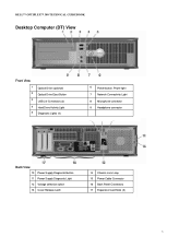
DELL™ OPTIPLEX™ 380 TECHNICAL GUIDEBOOK Desktop Computer (DT) View Front View 1 2 3 4 5 Optical Drive (optional) Optical Drive Eject Button USB 2.0 Connectors (2) Hard Drive Activity Light Diagnostic Lights (4) 6 Power button, Power light 7 Network Connectivity Light 8 Microphone connector 9 Headphone connector Back View 10 Power Supply Diagnostic Button 11 Power Supply Diagnostic Light 12 Voltage selection switch 13 Cover Release Latch 14 Chassis Lock Loop 15 Power Cable Connector 16 Back Panel Connectors 17 Expansion Card Slots (3) 5
DELL™ OPTIPLEX™ 380 TECHNICAL GUIDEBOOK Desktop Computer (DT) View Front View 1 2 3 4 5 Optical Drive (optional) Optical Drive Eject Button USB 2.0 Connectors (2) Hard Drive Activity Light Diagnostic Lights (4) 6 Power button, Power light 7 Network Connectivity Light 8 Microphone connector 9 Headphone connector Back View 10 Power Supply Diagnostic Button 11 Power Supply Diagnostic Light 12 Voltage selection switch 13 Cover Release Latch 14 Chassis Lock Loop 15 Power Cable Connector 16 Back Panel Connectors 17 Expansion Card Slots (3) 5
Guidebook
Page 6
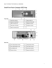
DELL™ OPTIPLEX™ 380 TECHNICAL GUIDEBOOK Small Form Factor Computer (SFF) View Front View 1 Optical Drive (optional) 2 Optical Drive Eject Button 3 USB 2.0 Connectors (2) 4 Power button, Power light 5 Network Connectivity Light 6 Diagnostic lights (4) 7 Hard Drive Activity Light 8 Headphone connector 9 Microphone connector Back View 10 Power Supply Diagnostic Button 11 Power Supply Diagnostic Light 12 Cover Release Latch 13 Chassis Lock Loop 14 Voltage Selection Switch 15 Power Cable Connector 16 Back Panel Connectors 17 Expansion Card Slots (3) 6
DELL™ OPTIPLEX™ 380 TECHNICAL GUIDEBOOK Small Form Factor Computer (SFF) View Front View 1 Optical Drive (optional) 2 Optical Drive Eject Button 3 USB 2.0 Connectors (2) 4 Power button, Power light 5 Network Connectivity Light 6 Diagnostic lights (4) 7 Hard Drive Activity Light 8 Headphone connector 9 Microphone connector Back View 10 Power Supply Diagnostic Button 11 Power Supply Diagnostic Light 12 Cover Release Latch 13 Chassis Lock Loop 14 Voltage Selection Switch 15 Power Cable Connector 16 Back Panel Connectors 17 Expansion Card Slots (3) 6
Service Manual
Page 2
...cache, Processor ID, Microcode Version, Multi Core Capable and HT Capable 64-bit Technology.. Back to Contents Page System Setup Dell™ OptiPlex™ 380 Service Manual-Mini-Tower Boot Menu Navigation Keystrokes Entering System Setup System Setup Simulation System Setup Menu Options Boot Menu Press ... changes to change Cancel modification Reset defaults Navigation Keystrokes , left- Keystroke < > -Remain in this key, press when the keyboard lights first flash. This menu is useful when you are also included in Setup, Save/Exit, Discard/Exit Left or right-arrow key ...
...cache, Processor ID, Microcode Version, Multi Core Capable and HT Capable 64-bit Technology.. Back to Contents Page System Setup Dell™ OptiPlex™ 380 Service Manual-Mini-Tower Boot Menu Navigation Keystrokes Entering System Setup System Setup Simulation System Setup Menu Options Boot Menu Press ... changes to change Cancel modification Reset defaults Navigation Keystrokes , left- Keystroke < > -Remain in this key, press when the keyboard lights first flash. This menu is useful when you are also included in Setup, Save/Exit, Discard/Exit Left or right-arrow key ...
Service Manual
Page 11
... tests you want to test displays in the system setup program. 3. Back to Contents Page Diagnostics Dell™ OptiPlex™ 380 Service Manual-Desktop Dell Diagnostics Power Button Light Codes Beep Codes Diagnostic Lights Dell Diagnostics When to Use the Dell Diagnostics It is recommended that you print these procedures before you see the Windows desktop. Enter system...
... tests you want to test displays in the system setup program. 3. Back to Contents Page Diagnostics Dell™ OptiPlex™ 380 Service Manual-Desktop Dell Diagnostics Power Button Light Codes Beep Codes Diagnostic Lights Dell Diagnostics When to Use the Dell Diagnostics It is recommended that you print these procedures before you see the Windows desktop. Enter system...
Service Manual
Page 12
.... 3. Beep Codes If the monitor cannot display error messages during the POST. Contact Dell. 1. To exit the Dell Diagnostics and restart the computer, close the Main Menu screen. The power light states are detected Cause Possible system board failure. Ensure that may indicate requirements for more... run a test from the Drivers and Utilities disc, remove the disc. 5. Power Light State Description Off Power is off or is corrected. The following table for running the Dell Diagnostics from the Custom Test or Symptom Tree option, click the applicable tab described in...
.... 3. Beep Codes If the monitor cannot display error messages during the POST. Contact Dell. 1. To exit the Dell Diagnostics and restart the computer, close the Main Menu screen. The power light states are detected Cause Possible system board failure. Ensure that may indicate requirements for more... run a test from the Drivers and Utilities disc, remove the disc. 5. Power Light State Description Off Power is off or is corrected. The following table for running the Dell Diagnostics from the Custom Test or Symptom Tree option, click the applicable tab described in...
Service Manual
Page 13
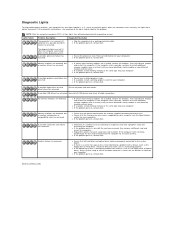
...of the same type into your computer. l If available, install working electrical outlet. l If the problem persists, contact Dell. Reseat all four lights turn off before turning off condition or a possible pre-BIOS failure has occurred. No memory modules are not lit after... modules are detected, but a memory configuration or compatibility error has occurred. Another failure has occurred. l If the problem persists, contact Dell. Light Pattern Problem Description The computer is supported by removing an expansion card (not a graphics card) and restarting the computer. If the computer...
...of the same type into your computer. l If available, install working electrical outlet. l If the problem persists, contact Dell. Reseat all four lights turn off before turning off condition or a possible pre-BIOS failure has occurred. No memory modules are not lit after... modules are detected, but a memory configuration or compatibility error has occurred. Another failure has occurred. l If the problem persists, contact Dell. Light Pattern Problem Description The computer is supported by removing an expansion card (not a graphics card) and restarting the computer. If the computer...


