Dell™ Technology Guide
Page 272
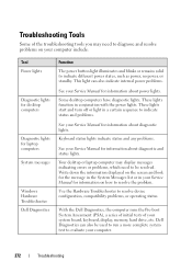
Troubleshooting Tools Some of your system board, keyboard, display, memory, hard drive, etc. Keyboard status lights indicate status and any problems. See your Service Manual for information on how to diagnose and ... the problem. These lights start and turn off or light in conjunction with the power lights. Dell Diagnostics can also indicate internal power problems. See your computer include: Tool Power lights Diagnostic lights for desktop computers Diagnostic lights for information about power lights. This light can also be resolved. Some desktop computers have diagnostic lights...
Troubleshooting Tools Some of your system board, keyboard, display, memory, hard drive, etc. Keyboard status lights indicate status and any problems. See your Service Manual for information on how to diagnose and ... the problem. These lights start and turn off or light in conjunction with the power lights. Dell Diagnostics can also indicate internal power problems. See your computer include: Tool Power lights Diagnostic lights for desktop computers Diagnostic lights for information about power lights. This light can also be resolved. Some desktop computers have diagnostic lights...

Dell™ Technology Guide
Page 274
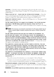
... interference are securely connected to the system board (see the documentation shipped with your location, if applicable. - Ensure that the processor power cable is securely connected to help identify the problem. 274 Troubleshooting Power, keyboard, and mouse extension cables - Ensure... Ensure that the voltage selection switch is receiving electrical power, but an internal power problem may be used to the system board (see the documentation shipped with another device, such as a lamp. - Multiple power strips connected to the same electrical outlet Diagnostic Lights for...
... interference are securely connected to the system board (see the documentation shipped with your location, if applicable. - Ensure that the processor power cable is securely connected to help identify the problem. 274 Troubleshooting Power, keyboard, and mouse extension cables - Ensure... Ensure that the voltage selection switch is receiving electrical power, but an internal power problem may be used to the system board (see the documentation shipped with another device, such as a lamp. - Multiple power strips connected to the same electrical outlet Diagnostic Lights for...
Dell™ Technology Guide
Page 278
...OR GREATER FOR BEST SYSTEM PERFORMANCE. Connect the correct AC adapter to the computer or docking station. Contact Dell for instructions, see "Contacting Dell" on page 308). THE AC POWER ADAPTER TYPE CANNOT BE DETERMINED. PRESS F5 TO RUN ONBOARD DIAGNOSTICS. - • Reseat the memory ...(for assistance (see your computer's Service Manual). • If memory was not removed or installed, memory module or system board failure ...
...OR GREATER FOR BEST SYSTEM PERFORMANCE. Connect the correct AC adapter to the computer or docking station. Contact Dell for instructions, see "Contacting Dell" on page 308). THE AC POWER ADAPTER TYPE CANNOT BE DETERMINED. PRESS F5 TO RUN ONBOARD DIAGNOSTICS. - • Reseat the memory ...(for assistance (see your computer's Service Manual). • If memory was not removed or installed, memory module or system board failure ...
Dell™ Technology Guide
Page 279
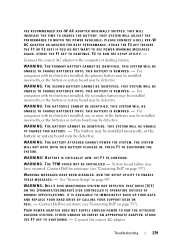
... E R Y I S R E M O V E D . - WARNING: THE BATTERY CANNOT BE IDENTIFIED. System board failure may be defective. WARNING: DELL'S DISK MONITORING SYSTEM HAS DETECTED THAT DRIVE [0/1] ON THE [PRIMARY/SECONDARY] EIDE CONTROLLER IS OPERATING OUTSIDE OF NORMAL SPECIFICATIONS. EITHER...POWER WARNING MESSAGES AGAIN. WARNING: THE SECOND BATTERY CANNOT BE IDENTIFIED. WARNING: THE BATTERIES CANNOT BE IDENTIFIED. THIS SYSTEM WILL BE UNABLE TO CHARGE THIS BATTERY. - The battery may be installed incorrectly, or the battery or system board may be defective. BATTERY IS CRITICALLY LOW. Contact Dell...
... E R Y I S R E M O V E D . - WARNING: THE BATTERY CANNOT BE IDENTIFIED. System board failure may be defective. WARNING: DELL'S DISK MONITORING SYSTEM HAS DETECTED THAT DRIVE [0/1] ON THE [PRIMARY/SECONDARY] EIDE CONTROLLER IS OPERATING OUTSIDE OF NORMAL SPECIFICATIONS. EITHER...POWER WARNING MESSAGES AGAIN. WARNING: THE SECOND BATTERY CANNOT BE IDENTIFIED. WARNING: THE BATTERIES CANNOT BE IDENTIFIED. THIS SYSTEM WILL BE UNABLE TO CHARGE THIS BATTERY. - The battery may be installed incorrectly, or the battery or system board may be defective. BATTERY IS CRITICALLY LOW. Contact Dell...
Dell™ Technology Guide
Page 282
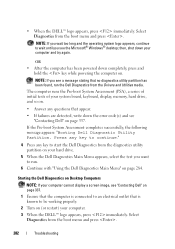
... from the boot menu and press . OR • After the computer has been powered down completely, press and hold the key while powering the computer on page 337. Press any key to run the Dell Diagnostics from the diagnostics utility partition on your hard drive. 5 When the...run . 6 Continue with "Using the Dell Diagnostics Main Menu" on (or restart) your system board, keyboard, display, memory, hard drive, and so on. • Answer any key to start the Dell Diagnostics from the Drivers and Utilities media. • When the DELL™ logo appears, press immediately. then...
... from the boot menu and press . OR • After the computer has been powered down completely, press and hold the key while powering the computer on page 337. Press any key to run the Dell Diagnostics from the diagnostics utility partition on your hard drive. 5 When the...run . 6 Continue with "Using the Dell Diagnostics Main Menu" on (or restart) your system board, keyboard, display, memory, hard drive, and so on. • Answer any key to start the Dell Diagnostics from the Drivers and Utilities media. • When the DELL™ logo appears, press immediately. then...
Dell™ Technology Guide
Page 297
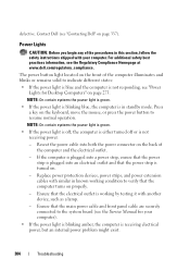
...; Ensure that all memory modules (see the documentation shipped with similar in standby mode. E L I M I N A T E I S O F F - NOTE: On certain systems the power light is green. I F T H E P O W E R L I G H T I S B L I N K I N G B L U E - The computer is securely connected to the system board power connector (POWER2) (see the Service Manual for your computer). • Remove and then reinstall any expansion cards, including graphics cards...
...; Ensure that all memory modules (see the documentation shipped with similar in standby mode. E L I M I N A T E I S O F F - NOTE: On certain systems the power light is green. I F T H E P O W E R L I G H T I S B L I N K I N G B L U E - The computer is securely connected to the system board power connector (POWER2) (see the Service Manual for your computer). • Remove and then reinstall any expansion cards, including graphics cards...
Dell™ Technology Guide
Page 304
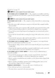
...the computer is not responding, see "Power Lights for Desktop Computers" on the keyboard, move the mouse, or press the power button to the system board (see the Service Manual for your computer. For additional safety best practices information, see "Contacting Dell" on properly. - If the ...computer is plugged into an electrical outlet and that the main power cable and front panel cable...
...the computer is not responding, see "Power Lights for Desktop Computers" on the keyboard, move the mouse, or press the power button to the system board (see the Service Manual for your computer. For additional safety best practices information, see "Contacting Dell" on properly. - If the ...computer is plugged into an electrical outlet and that the main power cable and front panel cable...
Dell™ Technology Guide
Page 305
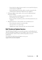
... Update Service The Dell Technical Update service provides proactive e-mail notification of interference are: - Ensure that the processor power cable is free and can be malfunctioning or incorrectly installed. - Some possible causes of software and hardware updates for your computer. • Eliminate interference. Multiple power strips connected to the system board (see the Documentation...
... Update Service The Dell Technical Update service provides proactive e-mail notification of interference are: - Ensure that the processor power cable is free and can be malfunctioning or incorrectly installed. - Some possible causes of software and hardware updates for your computer. • Eliminate interference. Multiple power strips connected to the system board (see the Documentation...
Dell™ Technology Guide
Page 350
...Shortcut icons do not change the location of rotations that can often be used to your computer when you access Dell Support at support.dell.com or when you call Dell for errors. A SIM card contains a microchip that keeps the date and time after it first. revolutions ... setup program - SIM - Some programs essential to the original SCSI parallel architecture). RTC - Battery-powered clock on your computer reside in rpm. SDRAM - A bar code label on the system board that encrypts voice and data transmissions. shortcut - An icon that is not affected. Also, you can...
...Shortcut icons do not change the location of rotations that can often be used to your computer when you access Dell Support at support.dell.com or when you call Dell for errors. A SIM card contains a microchip that keeps the date and time after it first. revolutions ... setup program - SIM - Some programs essential to the original SCSI parallel architecture). RTC - Battery-powered clock on your computer reside in rpm. SDRAM - A bar code label on the system board that encrypts voice and data transmissions. shortcut - An icon that is not affected. Also, you can...
Dell™ Technology Guide
Page 351
... cards and controllers that supports resolutions up to the computer. T TAPI - surge protectors - super-video graphics array - The main circuit board in the BIOS, such as those that serves as the motherboard. A utility that may occur during electrical storms. SVGA - telephony application ...- An audio transfer file format that shuts down all unnecessary computer operations to configure user-selectable options in your computer. A power management mode that allows the transfer of video memory installed in the computer. Strike Zone™ - Reinforced area of telephony ...
... cards and controllers that supports resolutions up to the computer. T TAPI - surge protectors - super-video graphics array - The main circuit board in the BIOS, such as those that serves as the motherboard. A utility that may occur during electrical storms. SVGA - telephony application ...- An audio transfer file format that shuts down all unnecessary computer operations to configure user-selectable options in your computer. A power management mode that allows the transfer of video memory installed in the computer. Strike Zone™ - Reinforced area of telephony ...
Dell™ Technology Guide
Page 352
... Text editors do not usually provide word wrap or formatting functionality (the option to underline, change fonts, and so on the system board (in computers with an integrated video controller) that provides the video capabilities-in to your computer. 352 UPS - UTP - System ...memory dynamically allocated to protect against interference. A backup power source used in to a multi-port hub that when combined with the monitor-for a low-speed device such as file and e-mail protection...
... Text editors do not usually provide word wrap or formatting functionality (the option to underline, change fonts, and so on the system board (in computers with an integrated video controller) that provides the video capabilities-in to your computer. 352 UPS - UTP - System ...memory dynamically allocated to protect against interference. A backup power source used in to a multi-port hub that when combined with the monitor-for a low-speed device such as file and e-mail protection...
Service Manual
Page 5
... attached devices. Disconnect all telephone or network cables from being scratched. 2. Turn the computer top-side up, open the display, and press the power button to prevent the computer cover from the computer. 4. Remove the battery (see Removing the Battery). 8. Disconnect your computer (see Removing the ... steps before working inside the computer. 7. Press and eject any installed cards from their electrical outlets. 6. Back to the system board, remove the main battery (see Turning Off Your Computer) and all attached devices from the 7-in-1 Media Card Reader. 5.
... attached devices. Disconnect all telephone or network cables from being scratched. 2. Turn the computer top-side up, open the display, and press the power button to prevent the computer cover from the computer. 4. Remove the battery (see Removing the Battery). 8. Disconnect your computer (see Removing the ... steps before working inside the computer. 7. Press and eject any installed cards from their electrical outlets. 6. Back to the system board, remove the main battery (see Turning Off Your Computer) and all attached devices from the 7-in-1 Media Card Reader. 5.
Service Manual
Page 41
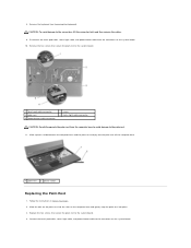
... the tabs on the palm rest into the slots on the system board. 10. Replace the five screws that secure the plam rest to the system board. 1 touch pad cable connector 3 palm rest 5 power button cable connector 2 screw 4 status light cable connector CAUTION: Carefully separate the palm rest from the ... base and gently snap the palm rest into place. 3. Disconnect the touch pad cable, status light cable, and power button cable from the computer base to avoid damage to the system board. 4. Remove the five screws that secure the plam rest to the palm rest. 11. Remove the keyboard (see...
... the tabs on the palm rest into the slots on the system board. 10. Replace the five screws that secure the plam rest to the system board. 1 touch pad cable connector 3 palm rest 5 power button cable connector 2 screw 4 status light cable connector CAUTION: Carefully separate the palm rest from the ... base and gently snap the palm rest into place. 3. Disconnect the touch pad cable, status light cable, and power button cable from the computer base to avoid damage to the system board. 4. Remove the five screws that secure the plam rest to the palm rest. 11. Remove the keyboard (see...


