TravelMate 240/250 Service Guide
Page 39
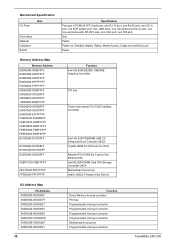
...-E01008FF E0100C00-E0100DFF E0200000-E02000FF FEBFFC00-FEBFFFFF FEC10000-FEC1FFFF FF000000-FFFFFFFF Function Intel (R) 82852/82855 GM/GME Graphics Controller PCI bus Texas Instruments PCI-1520 CardBus Controller Intel (R) 82801DB/DBM USB 2.0 Enhanced Host Controller-...Hub Device I/O Address Map I /O Ports Item Drive Bays Material Indicators Switch Specification Two type II PCMCIA (PC Card) port, one RJ-11 port, one RJ-45 port, one DC-in port, one ECP paralle port, four... controller Programmable interrupt controller Motherboard resources Programmable interrupt controller TravelMate 240/ 250
...-E01008FF E0100C00-E0100DFF E0200000-E02000FF FEBFFC00-FEBFFFFF FEC10000-FEC1FFFF FF000000-FFFFFFFF Function Intel (R) 82852/82855 GM/GME Graphics Controller PCI bus Texas Instruments PCI-1520 CardBus Controller Intel (R) 82801DB/DBM USB 2.0 Enhanced Host Controller-...Hub Device I/O Address Map I /O Ports Item Drive Bays Material Indicators Switch Specification Two type II PCMCIA (PC Card) port, one RJ-11 port, one RJ-45 port, one DC-in port, one ECP paralle port, four... controller Programmable interrupt controller Motherboard resources Programmable interrupt controller TravelMate 240/ 250
TravelMate 240/250 Service Guide
Page 59
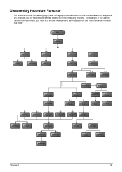
...you want to be removed during servicing. Disassembly Procedure Flowchart The flowchart on the succeeding page gives you a graphic representation on the entire disassembly sequence and instructs you must first remove the keyboard, then disassemble the inside assembly...Launch Board Lower Case Assembly *2 FDD Module *3 *3 *11 *4 RTC Battery *3 Mini PCI Card Plate Upper Case Assembly Disconnect Wireless LAN Antenna *4 Thermal Module *4 Wireless LAN Antenna Touchpad Cover Wireless LAN Card CPU ODD Module *4 HDD Bracket *1 ODD Support Bracket *1 CPU Heatsink Plate *3 VGA Heatsink ...
...you want to be removed during servicing. Disassembly Procedure Flowchart The flowchart on the succeeding page gives you a graphic representation on the entire disassembly sequence and instructs you must first remove the keyboard, then disassemble the inside assembly...Launch Board Lower Case Assembly *2 FDD Module *3 *3 *11 *4 RTC Battery *3 Mini PCI Card Plate Upper Case Assembly Disconnect Wireless LAN Antenna *4 Thermal Module *4 Wireless LAN Antenna Touchpad Cover Wireless LAN Card CPU ODD Module *4 HDD Bracket *1 ODD Support Bracket *1 CPU Heatsink Plate *3 VGA Heatsink ...


