TravelMate 240/250 Service Guide
Page 59
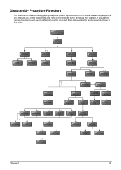
... the main board, you on the components that order. Start Battery HDD Module *2 HDD HDD Holder *2 Dimm Cover Memory *1 Modem Cover *2 Modem Board Hinge Caps *2 Middle Cover Keyboard *6 LCD Module *2 Launch Board Lower Case Assembly *2 FDD Module *3 *3 *11 *4 RTC Battery *3 Mini PCI Card Plate Upper Case Assembly Disconnect Wireless LAN Antenna *4 Thermal...
... the main board, you on the components that order. Start Battery HDD Module *2 HDD HDD Holder *2 Dimm Cover Memory *1 Modem Cover *2 Modem Board Hinge Caps *2 Middle Cover Keyboard *6 LCD Module *2 Launch Board Lower Case Assembly *2 FDD Module *3 *3 *11 *4 RTC Battery *3 Mini PCI Card Plate Upper Case Assembly Disconnect Wireless LAN Antenna *4 Thermal...

TravelMate 240/250 Service Guide
Page 65
.... 5. See "Removing the Battery" on page 56. To remove the middle cover, first use a plastic flat screwdriver to remove the right hinge cap. 3. Removing the Launch Board 1. Detach the middle cover from the machine. 7. See "Removing the Middle Cover" on page 52. 2. See "Removing the Battery" on ... main unit. . Then remove the screw holding the middle cover on page 52. 2. Remove the screw that secures the middle cover. 4. Chapter 3 56 Removing the LCD Module Removing the Middle Cover 1.
.... 5. See "Removing the Battery" on page 56. To remove the middle cover, first use a plastic flat screwdriver to remove the right hinge cap. 3. Removing the Launch Board 1. Detach the middle cover from the machine. 7. See "Removing the Middle Cover" on page 52. 2. See "Removing the Battery" on ... main unit. . Then remove the screw holding the middle cover on page 52. 2. Remove the screw that secures the middle cover. 4. Chapter 3 56 Removing the LCD Module Removing the Middle Cover 1.

TravelMate 240/250 Service Guide
Page 66
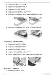
See "Removing the Middle Cover" on the left. 7. Remove the four screws holding the LCD hinge; Removing the LCD Module 1. Remove the screw that fastens the LCD coaxial cable and disconnect the cable. two on the right and two on the left . 6. two on the right and two on page 56. 4....page 52. 2. See "Removing the Battery" on the bottom; 3. Remove the two screws and then detach the launch board from the main unit. 57 TravelMate 240/ 250 See "Removing the Launch Board" on the left .Remove the four screws holding the LCD hinge; Then disconnect the LCD inverter cable. 5.
See "Removing the Middle Cover" on the left. 7. Remove the four screws holding the LCD hinge; Removing the LCD Module 1. Remove the screw that fastens the LCD coaxial cable and disconnect the cable. two on the right and two on the left . 6. two on the right and two on page 56. 4....page 52. 2. See "Removing the Battery" on the bottom; 3. Remove the two screws and then detach the launch board from the main unit. 57 TravelMate 240/ 250 See "Removing the Launch Board" on the left .Remove the four screws holding the LCD hinge; Then disconnect the LCD inverter cable. 5.

TravelMate 240/250 Service Guide
Page 69
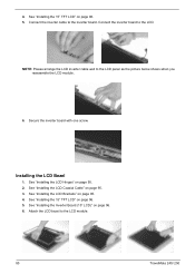
..." on page 56. 4. Chapter 3 60 NOTE: Please arrange the LCD inverter cable well to the LCD panel as the picture below shows when you reassemble the LCD module. To remove the LCD, first remove the four screws that secure the LCD hinges. 8. See "Removing the Launch Board" on page 52. See ..."Removing the Inverter Board (15" LCD)" on page 57. 5. See "Removing the LCD Module" on page 59. 7. See "...
..." on page 56. 4. Chapter 3 60 NOTE: Please arrange the LCD inverter cable well to the LCD panel as the picture below shows when you reassemble the LCD module. To remove the LCD, first remove the four screws that secure the LCD hinges. 8. See "Removing the Launch Board" on page 52. See ..."Removing the Inverter Board (15" LCD)" on page 57. 5. See "Removing the LCD Module" on page 59. 7. See "...
TravelMate 240/250 Service Guide
Page 70
...LCD Hinges 1. See "Removing the LCD Bezel" on page 56. 4. Remove the four screws holding the left bracket.. See "Removing the 15" TFT LCD" on page 57. 5. Remove the four screws holding the right LCD bracket.Then remove the right bracket. 9. Removing the LCD Coaxial Cable 1. See "Removing the LCD... page 60. 8. See "Removing the 15" TFT LCD" on page 52. 61 TravelMate 240/ 250 Then remove the left LCD bracket. See "Removing the Middle Cover" on page 59. 6. See "Removing the LCD Bezel" on page 56. 3. See "Removing the LCD Module" on page 56. 4. See "Removing the ...
...LCD Hinges 1. See "Removing the LCD Bezel" on page 56. 4. Remove the four screws holding the left bracket.. See "Removing the 15" TFT LCD" on page 57. 5. Remove the four screws holding the right LCD bracket.Then remove the right bracket. 9. Removing the LCD Coaxial Cable 1. See "Removing the LCD... page 60. 8. See "Removing the 15" TFT LCD" on page 52. 61 TravelMate 240/ 250 Then remove the left LCD bracket. See "Removing the Middle Cover" on page 59. 6. See "Removing the LCD Bezel" on page 56. 3. See "Removing the LCD Module" on page 56. 4. See "Removing the ...

TravelMate 240/250 Service Guide
Page 71
See "Removing the LCD Bezel" on page 57. 5. Remove the screw holding the left hinge, then remove the left hinge. See "Removing the LCD Module" on page 59. 6. Remove the screw holding the right hinge, then remove the right hinge. 9. See "Removing the Middle Cover" on page 56. 4. Chapter 3 62 See "Removing the Launch Board" on page 56. 3. See "Removing the Inverter Board (15" LCD)" on page 60. 8. See "Removing the 15" TFT LCD" on page 59. 7. 2.
See "Removing the LCD Bezel" on page 57. 5. Remove the screw holding the left hinge, then remove the left hinge. See "Removing the LCD Module" on page 59. 6. Remove the screw holding the right hinge, then remove the right hinge. 9. See "Removing the Middle Cover" on page 56. 4. Chapter 3 62 See "Removing the Launch Board" on page 56. 3. See "Removing the Inverter Board (15" LCD)" on page 60. 8. See "Removing the 15" TFT LCD" on page 59. 7. 2.
TravelMate 240/250 Service Guide
Page 92
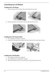
... the LCD Hinges" on page 95. 2. Attach the left LCD bracket with mylar. Installing the LCD Brackets 1. Fasten the LCD coaxial cable with four screws. 83 TravelMate 240/ 250 Then secure the left bracket to the LCD panel. Place the right hinge to the LCD. Assembling the LCD Module Installing the LCD Hinges 1. Place the left hinge with one screw. See "Installing the LCD Hinges" on...
... the LCD Hinges" on page 95. 2. Attach the left LCD bracket with mylar. Installing the LCD Brackets 1. Fasten the LCD coaxial cable with four screws. 83 TravelMate 240/ 250 Then secure the left bracket to the LCD panel. Place the right hinge to the LCD. Assembling the LCD Module Installing the LCD Hinges 1. Place the left hinge with one screw. See "Installing the LCD Hinges" on...

TravelMate 240/250 Service Guide
Page 93
..." on page 95. Place the LCD to the LCD. Installing the Inverter Board (15" LCD) 1. See "Installing the LCD Brackets" on page 95. 3. See "Installing the LCD Brackets" on page 95. 2. See "Installing the LCD Hinges" on page 95. 4. Secure the left hinge with four screws. Installing the 15" TFT LCD 1. See "Installing the LCD Hinges" on page 95. 3. Fasten the...
..." on page 95. Place the LCD to the LCD. Installing the Inverter Board (15" LCD) 1. See "Installing the LCD Brackets" on page 95. 3. See "Installing the LCD Brackets" on page 95. 2. See "Installing the LCD Hinges" on page 95. 4. Secure the left hinge with four screws. Installing the 15" TFT LCD 1. See "Installing the LCD Hinges" on page 95. 3. Fasten the...
TravelMate 240/250 Service Guide
Page 94
NOTE: Please arrange the LCD inverter cable well to the LCD module. 85 TravelMate 240/ 250 See "Installing the LCD Coaxial Cable" on page 96. 6. See "Installing the Inverter Board (15" LCD)" on page 95. 3. Attach the LCD bezel to the LCD panel as the picture below shows when you reassemble the LCD module. 6. See "Installing the LCD Brackets" on page...
NOTE: Please arrange the LCD inverter cable well to the LCD module. 85 TravelMate 240/ 250 See "Installing the LCD Coaxial Cable" on page 96. 6. See "Installing the Inverter Board (15" LCD)" on page 95. 3. Attach the LCD bezel to the LCD panel as the picture below shows when you reassemble the LCD module. 6. See "Installing the LCD Brackets" on page...
TravelMate 240/250 Service Guide
Page 96
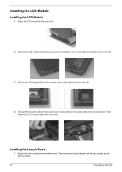
...two screws on the left . 3. Installing the Launch Board 1. Secure the LCD hinge with the two screws as the picture shows. 87 TravelMate 240/ 250 Place the LCD module to the maine board. one on the left . 4. Connect the LCD coaxial cable to the main unit. 2. Attach the launch board to the ...main board. Then secure the launch board with the four screws; Fasten the LCD module with one on...
...two screws on the left . 3. Installing the Launch Board 1. Secure the LCD hinge with the two screws as the picture shows. 87 TravelMate 240/ 250 Place the LCD module to the maine board. one on the left . 4. Connect the LCD coaxial cable to the main unit. 2. Attach the launch board to the ...main board. Then secure the launch board with the four screws; Fasten the LCD module with one on...

TravelMate 240/250 Service Guide
Page 97
Then close the LCD panel and fasten the middle cover with your fingers on page 99. 2. Attach the middle cover to the launch board. . 3. Secure the middle cover with one screw on another side as the picture shows. 5. Installing the Middle Cover 1. See "Installing the Launch Board" on its ridge. 4. Secure the middle cover with one screw as the picture shows. 7. Chapter 3 88 Connect the launch board cable to the main unit carefully. Then attach the left hinge cap. 6. Then attach the right hinge cap.
Then close the LCD panel and fasten the middle cover with your fingers on page 99. 2. Attach the middle cover to the launch board. . 3. Secure the middle cover with one screw on another side as the picture shows. 5. Installing the Middle Cover 1. See "Installing the Launch Board" on its ridge. 4. Secure the middle cover with one screw as the picture shows. 7. Chapter 3 88 Connect the launch board cable to the main unit carefully. Then attach the left hinge cap. 6. Then attach the right hinge cap.

TravelMate 240/250 Service Guide
Page 130
Picture No. Partname And Description INVERTER CABLE Part Number 50.T30V1.007 LCD COAXIAL CABLE 50.T30V1.008 NS LCD PANEL W/HINGE & LOGO 60.T30V1.008 Main Board Miscellaneous 121 NS LCD BEZEL 14.1" W/ICON LABEL 60.T30V1.006 LCD BEZEL 15" W/ICON LABEL 60.T30V1.007 HINGE PACK 6K.T30V1.001 MAINBOARD W/LAUNCH CABLE & MODEM & MODEM CABLE & PCMCIA SLOT & RTC BATTERY MB.T3001.001 LOGO 31.42S08.001 ICON LABEL TOUCHPAD SCROLL KEY 40.T30V1.001 42.T30V1.007 TravelMate 240/250
Picture No. Partname And Description INVERTER CABLE Part Number 50.T30V1.007 LCD COAXIAL CABLE 50.T30V1.008 NS LCD PANEL W/HINGE & LOGO 60.T30V1.008 Main Board Miscellaneous 121 NS LCD BEZEL 14.1" W/ICON LABEL 60.T30V1.006 LCD BEZEL 15" W/ICON LABEL 60.T30V1.007 HINGE PACK 6K.T30V1.001 MAINBOARD W/LAUNCH CABLE & MODEM & MODEM CABLE & PCMCIA SLOT & RTC BATTERY MB.T3001.001 LOGO 31.42S08.001 ICON LABEL TOUCHPAD SCROLL KEY 40.T30V1.001 42.T30V1.007 TravelMate 240/250


