TravelMate 240/250 Service Guide
Page 7
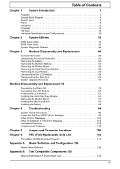
...of Contents Chapter 1 System Introduction 1 Features 1 System Block Diagram 3 Board Layout 4 Panel 6 Indicators 12 Keyboard 14 Hot Keys 16 Hardware Specifications and Configurations 19 Chapter 2 System Utilities 34 BIOS Setup Utility 34 BIOS ... 103 Intermittent Problems 106 Undetermined Problems 107 Chapter 5 Jumper and Connector Locations 108 Chapter 6 FRU (Field Replaceable Unit) List 112 TravelMate 240/250 Exploded Diagram 113 Appendix A Model Definition and Configuration 126 Model Name Definition 126 Appendix B Test Compatible Components 128 Microsoft Windows XP...
...of Contents Chapter 1 System Introduction 1 Features 1 System Block Diagram 3 Board Layout 4 Panel 6 Indicators 12 Keyboard 14 Hot Keys 16 Hardware Specifications and Configurations 19 Chapter 2 System Utilities 34 BIOS Setup Utility 34 BIOS ... 103 Intermittent Problems 106 Undetermined Problems 107 Chapter 5 Jumper and Connector Locations 108 Chapter 6 FRU (Field Replaceable Unit) List 112 TravelMate 240/250 Exploded Diagram 113 Appendix A Model Definition and Configuration 126 Model Name Definition 126 Appendix B Test Compatible Components 128 Microsoft Windows XP...
TravelMate 240/250 Service Guide
Page 10
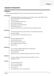
... wireless LAN option T Bluetooth option Multimedia T T T T All-in-one design (CD-ROM, floppy disk drive, hard disk drive) Sleek, smooth and stylish design Full-sized keyboard Ergonomically centered touchpad pointing device with 3D sound and wavetable synthesizer Built-in port One line-out port Two CardBus type II slot (3.3V and...
... wireless LAN option T Bluetooth option Multimedia T T T T All-in-one design (CD-ROM, floppy disk drive, hard disk drive) Sleek, smooth and stylish design Full-sized keyboard Ergonomically centered touchpad pointing device with 3D sound and wavetable synthesizer Built-in port One line-out port Two CardBus type II slot (3.3V and...
TravelMate 240/250 Service Guide
Page 13
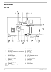
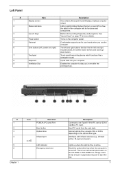
... 16 14 20 15 1 CPU Socket 14 2 Fan Connector 15 3 SW1 (Please see Chapter 5 for detailed settings) 16 4 Touchpad Cable Connector 17 5 HDD Connector 18 6 Keyboard Connector 19 7 Speaker Cable Connector 20 8 Optical Drive Connector 21 9 South Bridge 22 10 FDD Connector 23 11 Launch Cable Connector 24 12 PCMCIA Slot... Four USB Ports VGA Port LCD Coaxial Cable Connector Mini PCI Connector RTC Battery Connector North Bridge Parallel Port DC-in Port LCD Lid Switch 4 TravelMate 240/ 250
... 16 14 20 15 1 CPU Socket 14 2 Fan Connector 15 3 SW1 (Please see Chapter 5 for detailed settings) 16 4 Touchpad Cable Connector 17 5 HDD Connector 18 6 Keyboard Connector 19 7 Speaker Cable Connector 20 8 Optical Drive Connector 21 9 South Bridge 22 10 FDD Connector 23 11 Launch Cable Connector 24 12 PCMCIA Slot... Four USB Ports VGA Port LCD Coaxial Cable Connector Mini PCI Connector RTC Battery Connector North Bridge Parallel Port DC-in Port LCD Lid Switch 4 TravelMate 240/ 250
TravelMate 240/250 Service Guide
Page 16
... up / down button. The left and right buttons function like a computer mouse. Touch-sensitive pointing device which functions like the left , center and right) Touchpad Keyboard Ventilation Slot Description Also called LCD (Liquid Crystal Display), displays computer output. accepts CDs or DVDs depending on the CD-ROM or DVD-ROM drive...
... up / down button. The left and right buttons function like a computer mouse. Touch-sensitive pointing device which functions like the left , center and right) Touchpad Keyboard Ventilation Slot Description Also called LCD (Liquid Crystal Display), displays computer output. accepts CDs or DVDs depending on the CD-ROM or DVD-ROM drive...
TravelMate 240/250 Service Guide
Page 23
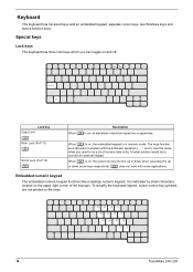
... are not printed on the upper right corner of numeric data entry. To simplify the keyboard legend, cursor-control key symbols are in numeric mode. When [ is indicated by small characters located on the keys. 14 TravelMate 240/ 250 Embedded numeric keypad The embedded numeric keypad functions like a desktop numeric keypad. A better solution...
... are not printed on the upper right corner of numeric data entry. To simplify the keyboard legend, cursor-control key symbols are in numeric mode. When [ is indicated by small characters located on the keys. 14 TravelMate 240/ 250 Embedded numeric keypad The embedded numeric keypad functions like a desktop numeric keypad. A better solution...
TravelMate 240/250 Service Guide
Page 24
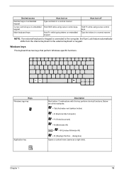
...(Finds Document) + M (Minimizes All) j+ + M (Undoes Minimize All) + R (Displays the Run... Desired access Number keys on embedded keypad Cursor-control keys on embedded keypad Main keyboard keys Num lock on embedded keypad. Hold Fn while typing letters on Type numbers in a normal manner. Windows keys The... keyboard has two keys that perform Windows-specific functions. Keys Windows logo key Application key Description Start button. Combinations with this key perform...
...(Finds Document) + M (Minimizes All) j+ + M (Undoes Minimize All) + R (Displays the Run... Desired access Number keys on embedded keypad Cursor-control keys on embedded keypad Main keyboard keys Num lock on embedded keypad. Hold Fn while typing letters on Type numbers in a normal manner. Windows keys The... keyboard has two keys that perform Windows-specific functions. Keys Windows logo key Application key Description Start button. Combinations with this key perform...

TravelMate 240/250 Service Guide
Page 26
...-{ Icon Function Brightness down Description Decreases the screen brightness. The Euro symbol If your keyboard layout is set to United States-international. Verify that the keyboard layout used for US keyboard users: The keyboard layout is set up Windows. Hold aGr and press the Euro symbol. aGr-Euro ...Euro Types the Euro symbol. Open a text editor or word processor. 3. To verify the keyboard type: 1. Fn-} End Functions as the g key. Click on the language tab and click on OK. Click on Details. 4. To type the...
...-{ Icon Function Brightness down Description Decreases the screen brightness. The Euro symbol If your keyboard layout is set to United States-international. Verify that the keyboard layout used for US keyboard users: The keyboard layout is set up Windows. Hold aGr and press the Euro symbol. aGr-Euro ...Euro Types the Euro symbol. Open a text editor or word processor. 3. To verify the keyboard type: 1. Fn-} End Functions as the g key. Click on the language tab and click on OK. Click on Details. 4. To type the...

TravelMate 240/250 Service Guide
Page 27
...) Bluetooth is used to launch the internet browser The mail button is enabled. TravelMate 240/ 250 These buttons are designated as wireless LAN/Bluetooth, Web Browser button, mail button, P1 andP2. Launch Keys Located at the top of the keyboard are users programmable. By default, P1 and P2 are five buttons. The Web...
...) Bluetooth is used to launch the internet browser The mail button is enabled. TravelMate 240/ 250 These buttons are designated as wireless LAN/Bluetooth, Web Browser button, mail button, P1 andP2. Launch Keys Located at the top of the keyboard are users programmable. By default, P1 and P2 are five buttons. The Web...
TravelMate 240/250 Service Guide
Page 28
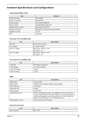
... ICH4 Mitsubish LPC keyboard controller M38857 TI 1520 Intel ICH4 Processor (for TravelMate 240) Item CPU type CPU package CPU core voltage CPU I/O voltage Specification Intel Cerelon processor To 2.0GHz uFCBGA High speed: 1.525V or 1.55V Low speed: 1.2V High speed: 1.525V or 1.55V Low speed: 1.2V Processor (for TravelMate 250) Item CPU type...
... ICH4 Mitsubish LPC keyboard controller M38857 TI 1520 Intel ICH4 Processor (for TravelMate 240) Item CPU type CPU package CPU core voltage CPU I/O voltage Specification Intel Cerelon processor To 2.0GHz uFCBGA High speed: 1.525V or 1.55V Low speed: 1.2V High speed: 1.525V or 1.55V Low speed: 1.2V Processor (for TravelMate 250) Item CPU type...
TravelMate 240/250 Service Guide
Page 35
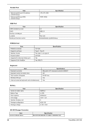
... Item Vendor & model name Battery Type Pack capacity Cell voltage Number of keypads Windows 95 keys Internal & external keyboard work simultaneously Specification Mitsubishi LPC keyboard controller M38857 API 84-/85- Parallel Port Item Optional parallel port I/O address (in BIOS Setup) Optional parallel port... 32 bit CardBus TZ 1520 Type II, Tpye III Two type II, one type III Left side Yes Yes (IRQ17) Specification Keyboard Item Keyboard controller Keyboard vendor & model name Total number of battery cell Package configuration Package voltage SIMPLO Li-ION 2000mAH 3.8V / 1.2V 8 4529 ...
... Item Vendor & model name Battery Type Pack capacity Cell voltage Number of keypads Windows 95 keys Internal & external keyboard work simultaneously Specification Mitsubishi LPC keyboard controller M38857 API 84-/85- Parallel Port Item Optional parallel port I/O address (in BIOS Setup) Optional parallel port... 32 bit CardBus TZ 1520 Type II, Tpye III Two type II, one type III Left side Yes Yes (IRQ17) Specification Keyboard Item Keyboard controller Keyboard vendor & model name Total number of battery cell Package configuration Package voltage SIMPLO Li-ION 2000mAH 3.8V / 1.2V 8 4529 ...
TravelMate 240/250 Service Guide
Page 36
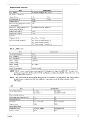
... LCD display area (diagonal, inch) Display technology Resolution Support colors Optical Specification Brightness control Contrast control 14.1" AU B141XN04 V2 14.1 TFT XGA (1024x768) 262K Keyboard hotkey None Specification 15" Hitachi TX38D85VC1CAB 15 TFT XGA (1024x768) 262K...
... LCD display area (diagonal, inch) Display technology Resolution Support colors Optical Specification Brightness control Contrast control 14.1" AU B141XN04 V2 14.1 TFT XGA (1024x768) 262K Keyboard hotkey None Specification 15" Hitachi TX38D85VC1CAB 15 TFT XGA (1024x768) 262K...
TravelMate 240/250 Service Guide
Page 38
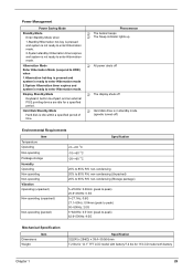
... expires and system is idle within a specified period of time. Hard Disk Standby Mode Hard disk is ready to enter Hibernation mode. Display Standby Mode Keyboard, built-in standby mode. (spindle turned-off T Hard disk drive is not ready to enter Hibernation mode. Power Management Power Saving Mode Standby Mode Enter...
... expires and system is idle within a specified period of time. Hard Disk Standby Mode Hard disk is ready to enter Hibernation mode. Display Standby Mode Keyboard, built-in standby mode. (spindle turned-off T Hard disk drive is not ready to enter Hibernation mode. Power Management Power Saving Mode Standby Mode Enter...
TravelMate 240/250 Service Guide
Page 41
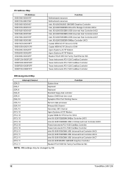
... (PCI) 10 (PCI) 10 (PCI) 10 (PCI) 10 (PCI) 10 (PCI) 10 (PCI) 11 (PCI) 11 (PCI) 11 (PCI) 11 (PCI) 11 Function System timer Keyboard Keyboard Standard floppy disk controller System CMOS/real time clock Synaptics PS/2 Port Pointing Device Numeric data processor Primary IDE Channel Secondary IDE Channel Agere Systems... Controller-24C7 Intel (R) 82852/82855 GM/GME Graphics Controller Realtek RTL8139/810x Family Fast Ethernet NIC NOTE: IRQ settings may be changed by OS 32 TravelMate 240/ 250
... (PCI) 10 (PCI) 10 (PCI) 10 (PCI) 10 (PCI) 10 (PCI) 10 (PCI) 11 (PCI) 11 (PCI) 11 (PCI) 11 (PCI) 11 Function System timer Keyboard Keyboard Standard floppy disk controller System CMOS/real time clock Synaptics PS/2 Port Pointing Device Numeric data processor Primary IDE Channel Secondary IDE Channel Agere Systems... Controller-24C7 Intel (R) 82852/82855 GM/GME Graphics Controller Realtek RTL8139/810x Family Fast Ethernet NIC NOTE: IRQ settings may be changed by OS 32 TravelMate 240/ 250
TravelMate 240/250 Service Guide
Page 59
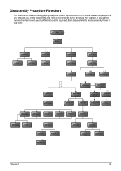
...board, you on the components that order. Start Battery HDD Module *2 HDD HDD Holder *2 Dimm Cover Memory *1 Modem Cover *2 Modem Board Hinge Caps *2 Middle Cover Keyboard *6 LCD Module *2 Launch Board Lower Case Assembly *2 FDD Module *3 *3 *11 *4 RTC Battery *3 Mini PCI Card Plate Upper Case Assembly Disconnect Wireless LAN Antenna... flowchart on the succeeding page gives you a graphic representation on the entire disassembly sequence and instructs you must first remove the keyboard, then disassemble the inside assembly frame in that need to be removed during servicing.
...board, you on the components that order. Start Battery HDD Module *2 HDD HDD Holder *2 Dimm Cover Memory *1 Modem Cover *2 Modem Board Hinge Caps *2 Middle Cover Keyboard *6 LCD Module *2 Launch Board Lower Case Assembly *2 FDD Module *3 *3 *11 *4 RTC Battery *3 Mini PCI Card Plate Upper Case Assembly Disconnect Wireless LAN Antenna... flowchart on the succeeding page gives you a graphic representation on the entire disassembly sequence and instructs you must first remove the keyboard, then disassemble the inside assembly frame in that need to be removed during servicing.
TravelMate 240/250 Service Guide
Page 72
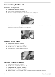
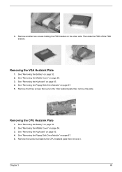
... page 56. 3. Remove the three screws holding the mini PCI card plate and remove the mini PCI card plate. 63 TravelMate 240/ 250 Use a plastic tweezers or a plastic flat screwdriver to expose the keyboard. 4. See "Removing the Battery" on page 52. 2. Removing the MimiPCI Card Plate 1. See "Removing the Battery" on page 52...
... page 56. 3. Remove the three screws holding the mini PCI card plate and remove the mini PCI card plate. 63 TravelMate 240/ 250 Use a plastic tweezers or a plastic flat screwdriver to expose the keyboard. 4. See "Removing the Battery" on page 52. 2. Removing the MimiPCI Card Plate 1. See "Removing the Battery" on page 52...

TravelMate 240/250 Service Guide
Page 73
..." on page 57. 4. Chapter 3 64 See "Removing the MimiPCI Card Plate" on page 63. 5. See "Removing the RTC Battery" on page 63. 6. See "Removing the Keyboard" on page 63. 6. Disconnect the fan cable then remove the four screws fastening the thermal module. 7. See "Removing the MimiPCI Card Plate" on page 63...
..." on page 57. 4. Chapter 3 64 See "Removing the MimiPCI Card Plate" on page 63. 5. See "Removing the RTC Battery" on page 63. 6. See "Removing the Keyboard" on page 63. 6. Disconnect the fan cable then remove the four screws fastening the thermal module. 7. See "Removing the MimiPCI Card Plate" on page 63...

TravelMate 240/250 Service Guide
Page 74
See "Removing the Thermal Module" on page 63. 6. Lift up the CPU lever, then place the CPU back to the upper case. 65 TravelMate 240/ 250 Then turn over the main unit and remove the 15 screws holding the lower case to the CPU socket. See "Removing the MimiPCI Card Plate" ... touchpad cable. 3. See "Removing the Middle Cover" on page 63. 5. See "Removing the Battery" on page 63. 4. Removing the Upper Case Assemly 1. See "Removing the Keyboard" on page 52. 2. Installing the Processor 1. See "Removing the...
See "Removing the Thermal Module" on page 63. 6. Lift up the CPU lever, then place the CPU back to the upper case. 65 TravelMate 240/ 250 Then turn over the main unit and remove the 15 screws holding the lower case to the CPU socket. See "Removing the MimiPCI Card Plate" ... touchpad cable. 3. See "Removing the Middle Cover" on page 63. 5. See "Removing the Battery" on page 63. 4. Removing the Upper Case Assemly 1. See "Removing the Keyboard" on page 52. 2. Installing the Processor 1. See "Removing the...
TravelMate 240/250 Service Guide
Page 75
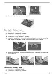
... the Middle Cover" on page 65. 5. Removing the Touchpad Cable 1. Chapter 3 66 Then take the upper case assembly off the main unit. See "Removing the Keyboard" on page 56. Finally remove the touchpad board from the touch pad board with a plastic tweezers.Then release the touchpad cover lock on the back...
... the Middle Cover" on page 65. 5. Removing the Touchpad Cable 1. Chapter 3 66 Then take the upper case assembly off the main unit. See "Removing the Keyboard" on page 56. Finally remove the touchpad board from the touch pad board with a plastic tweezers.Then release the touchpad cover lock on the back...
TravelMate 240/250 Service Guide
Page 76
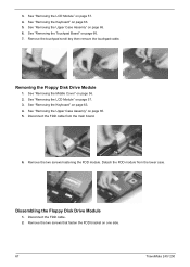
... the Floppy Disk Drive Module 1. Dissembling the Floppy Disk Drive Module 1. See "Removing the Upper Case Assemly" on one side. 67 TravelMate 240/ 250 Remove the touchpad scroll key then remove the touchpad cable. Remove the two screws that fasten the FDD bracket on page 65. 6. Remove... the FDD module. Disconnect the FDD cable. 2. See "Removing the Keyboard" on page 57. 3. See "Removing the LCD Module" on page 63. 4. See "Removing the Upper Case Assemly" on page 63. 5. See "Removing the Keyboard" on page 65. 5. Disconnect the FDD cable from the lower case...
... the Floppy Disk Drive Module 1. Dissembling the Floppy Disk Drive Module 1. See "Removing the Upper Case Assemly" on one side. 67 TravelMate 240/ 250 Remove the touchpad scroll key then remove the touchpad cable. Remove the two screws that fasten the FDD bracket on page 65. 6. Remove... the FDD module. Disconnect the FDD cable. 2. See "Removing the Keyboard" on page 57. 3. See "Removing the LCD Module" on page 63. 4. See "Removing the Upper Case Assemly" on page 63. 5. See "Removing the Keyboard" on page 65. 5. Disconnect the FDD cable from the lower case...
TravelMate 240/250 Service Guide
Page 77
... Battery" on page 52. 2. See "Removing the Battery" on page 52. 2. Remove another two screws holding the FDD bracket on page 63. 4. See "Removing the Keyboard" on the other side. See "Removing the Floppy Disk Drive Module" on page 56. 3. Then take the FDD off the FDD bracket. Removing the CPU...
... Battery" on page 52. 2. See "Removing the Battery" on page 52. 2. Remove another two screws holding the FDD bracket on page 63. 4. See "Removing the Keyboard" on the other side. See "Removing the Floppy Disk Drive Module" on page 56. 3. Then take the FDD off the FDD bracket. Removing the CPU...


