TravelMate 240/250 Service Guide
Page 7
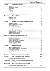
...System Diagnostic Diskette 46 Chapter 3 Machine Disassembly and Replacement 48 General Information 49 Disassembly Procedure Flowchart 50 Removing the Battery 52 Removing the Memory Module 53 Removing the Modem Board 54 Removing the Hard Disk Drive Module 55 Removing the... Problems 106 Undetermined Problems 107 Chapter 5 Jumper and Connector Locations 108 Chapter 6 FRU (Field Replaceable Unit) List 112 TravelMate 240/250 Exploded Diagram 113 Appendix A Model Definition and Configuration 126 Model Name Definition 126 Appendix B Test Compatible Components 128 Microsoft ...
...System Diagnostic Diskette 46 Chapter 3 Machine Disassembly and Replacement 48 General Information 49 Disassembly Procedure Flowchart 50 Removing the Battery 52 Removing the Memory Module 53 Removing the Modem Board 54 Removing the Hard Disk Drive Module 55 Removing the... Problems 106 Undetermined Problems 107 Chapter 5 Jumper and Connector Locations 108 Chapter 6 FRU (Field Replaceable Unit) List 112 TravelMate 240/250 Exploded Diagram 113 Appendix A Model Definition and Configuration 126 Model Name Definition 126 Appendix B Test Compatible Components 128 Microsoft ...
TravelMate 240/250 Service Guide
Page 10
...-out port Two CardBus type II slot (3.3V and 5V support) Chapter 1 1 T Built-in floppy diskette drive T High-capacity, Enhanced-IDE hard disk T High-capacity battery pack T Advanced Configuration Power Interface (ACPI) power management system Multimedia T T T 16-bit high-fidelity AC'97 stereo audio with Internet scroll key Expansion T T Two type...
...-out port Two CardBus type II slot (3.3V and 5V support) Chapter 1 1 T Built-in floppy diskette drive T High-capacity, Enhanced-IDE hard disk T High-capacity battery pack T Advanced Configuration Power Interface (ACPI) power management system Multimedia T T T 16-bit high-fidelity AC'97 stereo audio with Internet scroll key Expansion T T Two type...
TravelMate 240/250 Service Guide
Page 13
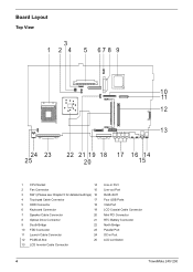
... LCD Inverter Cable Connector Line-in Port Line-out Port RJ45+RJ11 Four USB Ports VGA Port LCD Coaxial Cable Connector Mini PCI Connector RTC Battery Connector North Bridge Parallel Port DC-in Port LCD Lid Switch 4 TravelMate 240/ 250
... LCD Inverter Cable Connector Line-in Port Line-out Port RJ45+RJ11 Four USB Ports VGA Port LCD Coaxial Cable Connector Mini PCI Connector RTC Battery Connector North Bridge Parallel Port DC-in Port LCD Lid Switch 4 TravelMate 240/ 250

TravelMate 240/250 Service Guide
Page 20
Houses the computer's main memory. Chapter 1 11 Bottom Panel # 1 2 3 Item Battery bay Battery release latch Memory compartment Description Houses the computer's battery pack. Unlatches the battery to remove the battery pack.
Houses the computer's main memory. Chapter 1 11 Bottom Panel # 1 2 3 Item Battery bay Battery release latch Memory compartment Description Houses the computer's battery pack. Unlatches the battery to remove the battery pack.
TravelMate 240/250 Service Guide
Page 21
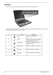
... when the floppy drive, hard disk or optical drive is active. 4 Battery Charge Lights when the battery is being charged. 5 Caps Lock Lights when Caps Lock is activated. 6 Num Lock Lights when Numeric Lock is activated. (Fn-F11) 12 TravelMate 240/ 250 The Power and Standby status icons are visible even when you close...
... when the floppy drive, hard disk or optical drive is active. 4 Battery Charge Lights when the battery is being charged. 5 Caps Lock Lights when Caps Lock is activated. 6 Num Lock Lights when Numeric Lock is activated. (Fn-F11) 12 TravelMate 240/ 250 The Power and Standby status icons are visible even when you close...
TravelMate 240/250 Service Guide
Page 35
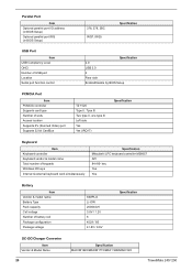
key Yes Yes Battery Item Vendor & model name Battery Type Pack capacity Cell voltage Number of keypads Windows 95 keys Internal & external keyboard work simultaneously Specification Mitsubishi LPC keyboard controller M38857 API 84-/85- ..., Tpye III Two type II, one type III Left side Yes Yes (IRQ17) Specification Keyboard Item Keyboard controller Keyboard vendor & model name Total number of battery cell Package configuration Package voltage SIMPLO Li-ION 2000mAH 3.8V / 1.2V 8 4529 / 8S 41.8V / 9.6V Specification DC-DC/Charger Converter Item Vendor & Model Name...
key Yes Yes Battery Item Vendor & model name Battery Type Pack capacity Cell voltage Number of keypads Windows 95 keys Internal & external keyboard work simultaneously Specification Mitsubishi LPC keyboard controller M38857 API 84-/85- ..., Tpye III Two type II, one type III Left side Yes Yes (IRQ17) Specification Keyboard Item Keyboard controller Keyboard vendor & model name Total number of battery cell Package configuration Package voltage SIMPLO Li-ION 2000mAH 3.8V / 1.2V 8 4529 / 8S 41.8V / 9.6V Specification DC-DC/Charger Converter Item Vendor & Model Name...
TravelMate 240/250 Service Guide
Page 36
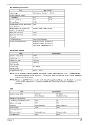
..., A) Charger Output Normal charge (charge while system is not operative) Background charge (charge even system is still operative) Battery-low 2 level (V) Battery-low 3 level (V) Protection Charger protection DC/DC converter protection Specification AC Adapter or Battery: 8V - 19VDC +5V 0~5A Li-ION 2.8A 3.3V 0~4A Constant power mode (2.8A~0A) 12.5V 11...
..., A) Charger Output Normal charge (charge while system is not operative) Background charge (charge even system is still operative) Battery-low 2 level (V) Battery-low 3 level (V) Protection Charger protection DC/DC converter protection Specification AC Adapter or Battery: 8V - 19VDC +5V 0~5A Li-ION 2.8A 3.3V 0~4A Constant power mode (2.8A~0A) 12.5V 11...
TravelMate 240/250 Service Guide
Page 38
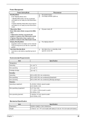
... is ready to peak) 62.6~500Hz: 4.0G Mechanical Specification Dimensions Weight Item Specification 322(W) x 294(D) x 39.4~39.9(H)mm 7.2 Ibs for 14.1" TFT LCD model with battery/7.4 Ibs for a specified period. Hard Disk Standby Mode Hard disk is not ready to enter Hibernation mode. Power Management Power Saving Mode Standby Mode Enter... enter Hibernation mode 2.System Hibernation timer expires and system is in touchpad, and an external PS/2 pointing device are idle for 15"LCD model with battery Chapter 1 29
... is ready to peak) 62.6~500Hz: 4.0G Mechanical Specification Dimensions Weight Item Specification 322(W) x 294(D) x 39.4~39.9(H)mm 7.2 Ibs for 14.1" TFT LCD model with battery/7.4 Ibs for a specified period. Hard Disk Standby Mode Hard disk is not ready to enter Hibernation mode. Power Management Power Saving Mode Standby Mode Enter... enter Hibernation mode 2.System Hibernation timer expires and system is in touchpad, and an external PS/2 pointing device are idle for 15"LCD model with battery Chapter 1 29
TravelMate 240/250 Service Guide
Page 39
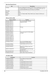
One Plastic Power-on, Standby, Battery Status, Media Access, CapsLock and NumLock Power Memory Address Map Memory Address 000A0000-000BFFFF E0000000-E007FFFF E0080000-E00FFFFF E8000000-EFFFFFFF F0000000-F7FFFFFF 000A0000-000BFFFF 000D0000-... 30 Function Direct Memory Access controller PCI bus Programmable interrupt controller Programmable interrupt controller Programmable interrupt controller Programmable interrupt controller Motherboard resources Programmable interrupt controller TravelMate 240/ 250
One Plastic Power-on, Standby, Battery Status, Media Access, CapsLock and NumLock Power Memory Address Map Memory Address 000A0000-000BFFFF E0000000-E007FFFF E0080000-E00FFFFF E8000000-EFFFFFFF F0000000-F7FFFFFF 000A0000-000BFFFF 000D0000-... 30 Function Direct Memory Access controller PCI bus Programmable interrupt controller Programmable interrupt controller Programmable interrupt controller Programmable interrupt controller Motherboard resources Programmable interrupt controller TravelMate 240/ 250
TravelMate 240/250 Service Guide
Page 55
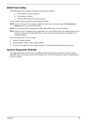
Copy the Phlash utilities to CSD website as soon as service CD released. The Phlash utility has auto-execution function. Acer HQ CSD will upload the utility to the bootable diskette. 3. System Diagnostic Diskette This diagnostic diskette is for the following ... run the Phlash. 1. If the battery pack does not contain enough power to update the system BIOS flash ROM. However, system diagnostic utility is not completely loaded. BIOS Flash Utility The BIOS flash memory update is required for the Acer TravelMate 240/250 series notebook machine. Use the Phlash...
Copy the Phlash utilities to CSD website as soon as service CD released. The Phlash utility has auto-execution function. Acer HQ CSD will upload the utility to the bootable diskette. 3. System Diagnostic Diskette This diagnostic diskette is for the following ... run the Phlash. 1. If the battery pack does not contain enough power to update the system BIOS flash ROM. However, system diagnostic utility is not completely loaded. BIOS Flash Utility The BIOS flash memory update is required for the Acer TravelMate 240/250 series notebook machine. Use the Phlash...
TravelMate 240/250 Service Guide
Page 59
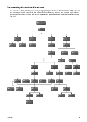
... keyboard, then disassemble the inside assembly frame in that need to remove the main board, you on the components that order. Start Battery HDD Module *2 HDD HDD Holder *2 Dimm Cover Memory *1 Modem Cover *2 Modem Board Hinge Caps *2 Middle Cover Keyboard *6 LCD... Module *2 Launch Board Lower Case Assembly *2 FDD Module *3 *3 *11 *4 RTC Battery *3 Mini PCI Card Plate Upper Case Assembly Disconnect Wireless LAN Antenna *4 Thermal Module *4 Wireless LAN Antenna Touchpad Cover Wireless LAN Card CPU ODD Module...
... keyboard, then disassemble the inside assembly frame in that need to remove the main board, you on the components that order. Start Battery HDD Module *2 HDD HDD Holder *2 Dimm Cover Memory *1 Modem Cover *2 Modem Board Hinge Caps *2 Middle Cover Keyboard *6 LCD... Module *2 Launch Board Lower Case Assembly *2 FDD Module *3 *3 *11 *4 RTC Battery *3 Mini PCI Card Plate Upper Case Assembly Disconnect Wireless LAN Antenna *4 Thermal Module *4 Wireless LAN Antenna Touchpad Cover Wireless LAN Card CPU ODD Module...

TravelMate 240/250 Service Guide
Page 61
Then slide the battery out from the machine. Chapter 3 52 Removing the Battery 1. To remove the battery, push the battery release latch. 2.
Then slide the battery out from the machine. Chapter 3 52 Removing the Battery 1. To remove the battery, push the battery release latch. 2.
TravelMate 240/250 Service Guide
Page 62
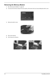
Remove the dimm cover. 4. Removing the Memory Module 1. To remove the memory module from the machine, first remove the two screws holding the dimm cover. 3. Pop up the memory. 5. Then remove the memory. 53 TravelMate 240/ 250 See "Removing the Battery" on page 52. 2.
Remove the dimm cover. 4. Removing the Memory Module 1. To remove the memory module from the machine, first remove the two screws holding the dimm cover. 3. Pop up the memory. 5. Then remove the memory. 53 TravelMate 240/ 250 See "Removing the Battery" on page 52. 2.

TravelMate 240/250 Service Guide
Page 63
To remove the modem board, first remove the screw from the modem board, then remove the modem board. Disconnect the modem cable from the modem cover. 3. Chapter 3 54 See "Removing the Battery" on the picture indicate. 5. Remove two screws from the main unit carefully by using a plastic bladed screw driver. 6. Then remove the modem board from the modem board as shown. Removing the Modem Board 1. Remove the modem cover from the machine. 4. Please remove the screws according to the number on page 52. 2.
To remove the modem board, first remove the screw from the modem board, then remove the modem board. Disconnect the modem cable from the modem cover. 3. Chapter 3 54 See "Removing the Battery" on the picture indicate. 5. Remove two screws from the main unit carefully by using a plastic bladed screw driver. 6. Then remove the modem board from the modem board as shown. Removing the Modem Board 1. Remove the modem cover from the machine. 4. Please remove the screws according to the number on page 52. 2.

TravelMate 240/250 Service Guide
Page 64
Disassembling the Hard Disk Drive Module 1. Remove the two screws that fasten the HDD holder. 4. See "Removing the Battery" on page 55. 3. See "Removing the Hard Disk Drive Module" on page 52. 2. Detach the hard disk drive from the HDD holder. 55 TravelMate 240/ 250 Then take the hard disk drive out of the main unit. Removing the Hard Disk Drive Module 1. To remove the hard disk drive, pull the hard disk dirve carefully. 3. See "Removing the Battery" on page 52. 2.
Disassembling the Hard Disk Drive Module 1. Remove the two screws that fasten the HDD holder. 4. See "Removing the Battery" on page 55. 3. See "Removing the Hard Disk Drive Module" on page 52. 2. Detach the hard disk drive from the HDD holder. 55 TravelMate 240/ 250 Then take the hard disk drive out of the main unit. Removing the Hard Disk Drive Module 1. To remove the hard disk drive, pull the hard disk dirve carefully. 3. See "Removing the Battery" on page 52. 2.

TravelMate 240/250 Service Guide
Page 65
See "Removing the Battery" on page 56. To remove the middle cover, first use a plastic flat screwdriver to remove the right hinge cap. 3. See "Removing the Middle Cover" on ... then remove the middle cover off the main unit. . Removing the Launch Board 1. Chapter 3 56 Detach the middle cover from the machine. 7. See "Removing the Battery" on the other side. 6. Then remove the screw holding the middle cover on page 52. 2. Removing the LCD Module Removing the Middle Cover 1.
See "Removing the Battery" on page 56. To remove the middle cover, first use a plastic flat screwdriver to remove the right hinge cap. 3. See "Removing the Middle Cover" on ... then remove the middle cover off the main unit. . Removing the Launch Board 1. Chapter 3 56 Detach the middle cover from the machine. 7. See "Removing the Battery" on the other side. 6. Then remove the screw holding the middle cover on page 52. 2. Removing the LCD Module Removing the Middle Cover 1.

TravelMate 240/250 Service Guide
Page 66
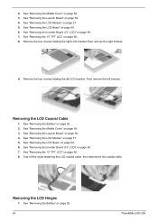
... and then detach the launch board from the main unit. 57 TravelMate 240/ 250 Removing the LCD Module 1. Remove the screw that fastens the LCD coaxial cable and disconnect the cable. Remove the four screws holding the LCD hinge; See "Removing the Battery" on page 56. 3. See "Removing the Middle Cover" on page...
... and then detach the launch board from the main unit. 57 TravelMate 240/ 250 Removing the LCD Module 1. Remove the screw that fastens the LCD coaxial cable and disconnect the cable. Remove the four screws holding the LCD hinge; See "Removing the Battery" on page 56. 3. See "Removing the Middle Cover" on page...
TravelMate 240/250 Service Guide
Page 68
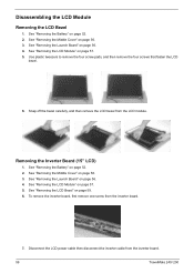
... page 57. 5. See "Removing the Launch Board" on page 57. 5. To remove the inverter board, first remove one screw from the inverter board. 59 TravelMate 240/ 250 Disassembling the LCD Module Removing the LCD Bezel 1. Disconnect the LCD power cable then disconnect the inverter cable from the inverter board. 7. Snap off the... LCD bezel from the LCD module. See "Removing the LCD Module" on page 56. 4. See "Removing the Middle Cover" on page 52. 2. See "Removing the Battery" on page 56. 3. See "Removing the...
... page 57. 5. See "Removing the Launch Board" on page 57. 5. To remove the inverter board, first remove one screw from the inverter board. 59 TravelMate 240/ 250 Disassembling the LCD Module Removing the LCD Bezel 1. Disconnect the LCD power cable then disconnect the inverter cable from the inverter board. 7. Snap off the... LCD bezel from the LCD module. See "Removing the LCD Module" on page 56. 4. See "Removing the Middle Cover" on page 52. 2. See "Removing the Battery" on page 56. 3. See "Removing the...

TravelMate 240/250 Service Guide
Page 69
... the four screws that secure the LCD hinges. 8. See "Removing the Inverter Board (15" LCD)" on page 56. 4. Removing the LCD Brackets 1. See "Removing the Battery" on page 57. 5. See "Removing the LCD Module" on page 52. 2. NOTE: Please arrange the LCD inverter cable well to the LCD panel as the... when you reassemble the LCD module. See "Removing the Middle Cover" on page 59. 6. See "Removing the LCD Bezel" on page 56. 3. See "Removing the Battery" on page 52.
... the four screws that secure the LCD hinges. 8. See "Removing the Inverter Board (15" LCD)" on page 56. 4. Removing the LCD Brackets 1. See "Removing the Battery" on page 57. 5. See "Removing the LCD Module" on page 52. 2. NOTE: Please arrange the LCD inverter cable well to the LCD panel as the... when you reassemble the LCD module. See "Removing the Middle Cover" on page 59. 6. See "Removing the LCD Bezel" on page 56. 3. See "Removing the Battery" on page 52.
TravelMate 240/250 Service Guide
Page 70
.... 6. Remove the four screws holding the left bracket.. See "Removing the Battery" on page 60. 8. See "Removing the 15" TFT LCD" on page 52. 2. See "Removing the Battery" on page 59. 6. See "Removing the LCD Bezel" on page 52. 61 TravelMate 240/ 250 See "Removing the Middle Cover" on page 56. 4. Removing the LCD...
.... 6. Remove the four screws holding the left bracket.. See "Removing the Battery" on page 60. 8. See "Removing the 15" TFT LCD" on page 52. 2. See "Removing the Battery" on page 59. 6. See "Removing the LCD Bezel" on page 52. 61 TravelMate 240/ 250 See "Removing the Middle Cover" on page 56. 4. Removing the LCD...


