
Uk Manual
Page 1
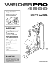
... equipment. Serial Number Decal (under seat) QUESTIONS? WEEVSY3426.1 Serial No. Write the serial number in this manual before using this manual for reference. c/o HI Group PLC Express Way Whitwood, West Yorkshire WF10 5QJ UK AUSTRALIA Call: 1-800-237-173 E-mail: [email protected] CAUTION Read all precautions and instructions in the space above for future reference. USERʼS MANUAL www.iconeurope.com Model No. If...
... equipment. Serial Number Decal (under seat) QUESTIONS? WEEVSY3426.1 Serial No. Write the serial number in this manual before using this manual for reference. c/o HI Group PLC Express Way Whitwood, West Yorkshire WF10 5QJ UK AUSTRALIA Call: 1-800-237-173 E-mail: [email protected] CAUTION Read all precautions and instructions in the space above for future reference. USERʼS MANUAL www.iconeurope.com Model No. If...
Uk Manual
Page 2
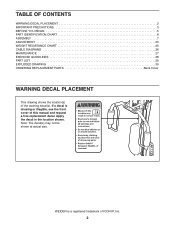
... of this manual and request a free replacement decal. WEIDER is missing or illegible, see the front cover of ICON IP, Inc. 2 Note: The decal(s) may not be shown at actual size. TABLE OF CONTENTS WARNING DECAL PLACEMENT 2 IMPORTANT PRECAUTIONS 3 BEFORE YOU BEGIN 5 PART IDENTIFICATION CHART 6 ASSEMBLY 7 ADJUSTMENT 23 WEIGHT RESISTANCE CHART 25 CABLE DIAGRAMS 26 MAINTENANCE 27 EXERCISE GUIDELINES 28 PART LIST 29 EXPLODED DRAWING 30 ORDERING REPLACEMENT PARTS Back Cover WARNING DECAL...
... of this manual and request a free replacement decal. WEIDER is missing or illegible, see the front cover of ICON IP, Inc. 2 Note: The decal(s) may not be shown at actual size. TABLE OF CONTENTS WARNING DECAL PLACEMENT 2 IMPORTANT PRECAUTIONS 3 BEFORE YOU BEGIN 5 PART IDENTIFICATION CHART 6 ASSEMBLY 7 ADJUSTMENT 23 WEIGHT RESISTANCE CHART 25 CABLE DIAGRAMS 26 MAINTENANCE 27 EXERCISE GUIDELINES 28 PART LIST 29 EXPLODED DRAWING 30 ORDERING REPLACEMENT PARTS Back Cover WARNING DECAL...
Uk Manual
Page 3
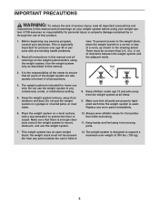
... this manual. Keep the weight system indoors, away from moving parts. 7. Read all instructions in this manual and all warnings on your weight system before using your physician. There must not be no responsibility for foot protection while exercising. 11. Do not put the weight system in any exercise program, consult your weight sys- Place the weight system on a level surface, with pre-existing health problems...
... this manual. Keep the weight system indoors, away from moving parts. 7. Read all instructions in this manual and all warnings on your weight system before using your physician. There must not be no responsibility for foot protection while exercising. 11. Do not put the weight system in any exercise program, consult your weight sys- Place the weight system on a level surface, with pre-existing health problems...
Uk Manual
Page 4
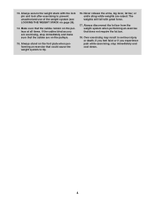
... death. Always disconnect the lat bar from the weight system when performing an exercise that could cause the weight system to prevent unauthorized use of the weight system (see LOCKING THE WEIGHT STACK on the pulleys at all times. Always secure the weight stack with great force. 17. If the cables bind as you experience pain while exercising, stop immediately and make sure...
... death. Always disconnect the lat bar from the weight system when performing an exercise that could cause the weight system to prevent unauthorized use of the weight system (see LOCKING THE WEIGHT STACK on the pulleys at all times. Always secure the weight stack with great force. 17. If the cables bind as you experience pain while exercising, stop immediately and make sure...
Uk Manual
Page 5
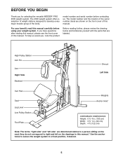
... questions after reading this manual, please see the front cover of this manual carefully before contacting us assist you for selecting the versatile WEIDER® PRO 4500 weight system. model number and serial number before using your benefit, read this manual. High Pulley Station Arm Pin Arm Right Side Backrest Shroud Left Side Curl Pad Seat Leg Lever Low Pulley Station Foot Plate Weights Anchor Hole* ASSEMBLED DIMENSIONS: Height: 6 ft. 4 in. (193...
... questions after reading this manual, please see the front cover of this manual carefully before contacting us assist you for selecting the versatile WEIDER® PRO 4500 weight system. model number and serial number before using your benefit, read this manual. High Pulley Station Arm Pin Arm Right Side Backrest Shroud Left Side Curl Pad Seat Leg Lever Low Pulley Station Foot Plate Weights Anchor Hole* ASSEMBLED DIMENSIONS: Height: 6 ft. 4 in. (193...
Uk Manual
Page 6
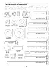
Note: If a part is the key number of the part, from the PART LIST near the end of this manual. PART IDENTIFICATION CHART Refer to the drawings below to identify small parts used in the hardware kit, check to see if it has been preattached. M8 Locknut (58) M10 Locknut (56) M12 Nut (86) M10 x 55mm Bolt (66) M10 x 65mm Bolt (75) M6 Washer...
Note: If a part is the key number of the part, from the PART LIST near the end of this manual. PART IDENTIFICATION CHART Refer to the drawings below to identify small parts used in the hardware kit, check to see if it has been preattached. M8 Locknut (58) M10 Locknut (56) M12 Nut (86) M10 x 55mm Bolt (66) M10 x 65mm Bolt (75) M6 Washer...
Uk Manual
Page 7
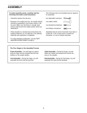
... connect the arms to walk around the weight system while you assemble it will attach the cables and pulleys that form the skeleton of the weight system. Arm Assembly-During this stage, you will be used. Seat Assembly-During the final stage, you will assemble the arms and the leg lever. one rubber mallet one standard screwdriver one Phillips screwdriver • Place all parts in the location where it . two adjustable...
... connect the arms to walk around the weight system while you assemble it will attach the cables and pulleys that form the skeleton of the weight system. Arm Assembly-During this stage, you will be used. Seat Assembly-During the final stage, you will assemble the arms and the leg lever. one rubber mallet one standard screwdriver one Phillips screwdriver • Place all parts in the location where it . two adjustable...

Uk Manual
Page 12
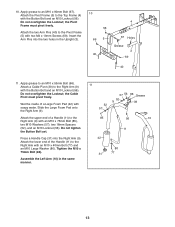
Tighten the Locknuts (56, 58) 69 17 used in these steps. 69 Bracket 2 69 Arm Assembly 9. Apply grease to the Front Leg (7) with two M4 x 19mm Screws (69). Attach the Shroud (17) to the Top Frame (4) with two M4 x 19mm Screws (69). 8 4 Attach the Shroud (17) to the brackets on the side shown. Orient the Leg... Lever (8) so that the brackets are inside the 69 Shroud. the Leg Lever must pivot freely. 9 73 8 Welded Support 7 Grease 73 12 Do not overtighten the Bolt Set; Attach the Leg Lever to the M10 x 70mm Bolt Set (73). Make sure that the welded support is ...
Tighten the Locknuts (56, 58) 69 17 used in these steps. 69 Bracket 2 69 Arm Assembly 9. Apply grease to the Front Leg (7) with two M4 x 19mm Screws (69). Attach the Shroud (17) to the Top Frame (4) with two M4 x 19mm Screws (69). 8 4 Attach the Shroud (17) to the brackets on the side shown. Orient the Leg... Lever (8) so that the brackets are inside the 69 Shroud. the Leg Lever must pivot freely. 9 73 8 Welded Support 7 Grease 73 12 Do not overtighten the Bolt Set; Attach the Leg Lever to the M10 x 70mm Bolt Set (73). Make sure that the welded support is ...
Uk Manual
Page 13
...Bolt (67). Attach the lower end of a Large Foam Pad (42) with the Button Bolt and an M10 Locknut (56). Apply grease to the Right Arm (9) with soapy water. the Pivot Frame must pivot freely. the Cable Pivot must pivot freely. Assemble the Left Arm (10) in the Upright (3). 10 56 69 5 40 4 67 Holes Grease 3 69 40 11. Insert the Arm Pins... with two M4 x 19mm Screws (69). Tighten the M10 x 75mm Bolt (85). 10. Attach the two Arm Pins (40) to an M10 x 55mm Bolt (66). Apply grease to the Pivot Frame (5) with the Button Bolt and an M10 Locknut (56). Press a Handle Cap (31) ...
...Bolt (67). Attach the lower end of a Large Foam Pad (42) with the Button Bolt and an M10 Locknut (56). Apply grease to the Right Arm (9) with soapy water. the Pivot Frame must pivot freely. the Cable Pivot must pivot freely. Assemble the Left Arm (10) in the Upright (3). 10 56 69 5 40 4 67 Holes Grease 3 69 40 11. Insert the Arm Pins... with two M4 x 19mm Screws (69). Tighten the M10 x 75mm Bolt (85). 10. Attach the two Arm Pins (40) to an M10 x 55mm Bolt (66). Apply grease to the Pivot Frame (5) with the Button Bolt and an M10 Locknut (56). Press a Handle Cap (31) ...
Uk Manual
Page 14
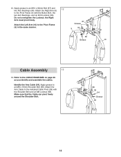
the Right Arm must pivot freely. Apply grease to the CABLE DIAGRAMS on page 26 as you identify and assemble the cables. Attach the Right Arm (9) 12 to the indicated Cable Pivot (39) with the Button Bolt, the two Arm Bushings, and an M10 Locknut (56). Refer to an M8 x 19mm Shoulder Bolt (65). Attach the Arm Cable to the Pivot Frame (5) with the Shoulder Bolt and an...
the Right Arm must pivot freely. Apply grease to the CABLE DIAGRAMS on page 26 as you identify and assemble the cables. Attach the Right Arm (9) 12 to the indicated Cable Pivot (39) with the Button Bolt, the two Arm Bushings, and an M10 Locknut (56). Refer to an M8 x 19mm Shoulder Bolt (65). Attach the Arm Cable to the Pivot Frame (5) with the Shoulder Bolt and an...
Uk Manual
Page 17
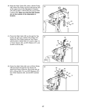
...x 80mm Bolt (71) used in step 19, a 19mm Spacer (33), an M10 Washer (57), and an M10 Locknut (56). 55 56 43 48 43 81 45 55 56 33 47 4 57 71 22. bracket. 21. Make sure that the Half Guards are on the outside of the Adjustable U- Route the High Cable (55...) up through the Top Frame (4). 22 Attach the Pulley inside the Top Frame with an M10 x 45mm Bolt (81) and an M10 Locknut (56). Wrap the High Cable (55) under a 90mm Pulley (48). Route the High Cable (55) over a 90mm Pulley (48) and down through the...
...x 80mm Bolt (71) used in step 19, a 19mm Spacer (33), an M10 Washer (57), and an M10 Locknut (56). 55 56 43 48 43 81 45 55 56 33 47 4 57 71 22. bracket. 21. Make sure that the Half Guards are on the outside of the Adjustable U- Route the High Cable (55...) up through the Top Frame (4). 22 Attach the Pulley inside the Top Frame with an M10 x 45mm Bolt (81) and an M10 Locknut (56). Wrap the High Cable (55) under a 90mm Pulley (48). Route the High Cable (55) over a 90mm Pulley (48) and down through the...
Uk Manual
Page 20
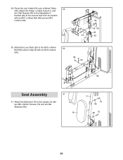
bracket (45) at the second hole from the bottom with an M10 Locknut 30 (56). 56 53 66 Seat Assembly 31 31. Attach the Low Cable (53) to the Upright (3) with two M6 x 80mm Screws (70) and two M6 Washers (82). 16 3 70 82 82 70 20 29. Attach the Backrest (16) to the M10 x 55mm Bolt (66) used in step 28 with an M10 x 55mm Bolt (66) and an M10 Locknut (56). 56 66 43 51 45 43 48 53 30. Route the Low Cable (53) over a 90mm Pulley 29 (48). Attach the Pulley, a Cable Trap (51), and two Half Guards (43) to the Adjustable U-
bracket (45) at the second hole from the bottom with an M10 Locknut 30 (56). 56 53 66 Seat Assembly 31 31. Attach the Low Cable (53) to the Upright (3) with two M6 x 80mm Screws (70) and two M6 Washers (82). 16 3 70 82 82 70 20 29. Attach the Backrest (16) to the M10 x 55mm Bolt (66) used in step 28 with an M10 x 55mm Bolt (66) and an M10 Locknut (56). 56 66 43 51 45 43 48 53 30. Route the Low Cable (53) over a 90mm Pulley 29 (48). Attach the Pulley, a Cable Trap (51), and two Half Guards (43) to the Adjustable U-
Uk Manual
Page 22
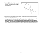
... MAINTENANCE on page 26 of the remaining parts will need to the Curl Post (13) with two M6 x 16mm Screws (62). 14 13 62 35. IMPORTANT: If the cables are closer to make sure that the cables move smoothly, find and correct the problem. If one of the cables does not move smoothly around the pulleys. The use of this manual for proper cable routing...
... MAINTENANCE on page 26 of the remaining parts will need to the Curl Post (13) with two M6 x 16mm Screws (62). 14 13 62 35. IMPORTANT: If the cables are closer to make sure that the cables move smoothly, find and correct the problem. If one of the cables does not move smoothly around the pulleys. The use of this manual for proper cable routing...
Uk Manual
Page 23
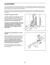
... benefit from the weight setting. The Lat Bar (not shown) or the Curl Bar (not shown) can be attached between the Ankle Strap and the Cable so that the Ankle Strap is used. CHANGING THE WEIGHT SETTING To change the setting of the Chain between the Ankle Strap and the Cable with two Cable Clips. Also, refer to the accompanying exercise guide to the cables and pulleys, the amount of resistance at each...
... benefit from the weight setting. The Lat Bar (not shown) or the Curl Bar (not shown) can be attached between the Ankle Strap and the Cable so that the Ankle Strap is used. CHANGING THE WEIGHT SETTING To change the setting of the Chain between the Ankle Strap and the Cable with two Cable Clips. Also, refer to the accompanying exercise guide to the cables and pulleys, the amount of resistance at each...
Uk Manual
Page 24
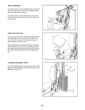
... weight system. When performing an exercise that does not require the Curl Pad (14), remove the Curl Pad and insert the 64mm Round Inner Cap (30) into the Front Leg and secure it in the Upright (3) and the Pivot Frame (5) as shown. To use the Arms (9, 10) as press arms, insert the Arm Pins ...(40) into the holes in the Pivot Frame (5) and the Arms. USING THE CURL PAD To use the Arms (9, 10) as butterfly arms, insert the Arm Pins (40) into ...
... weight system. When performing an exercise that does not require the Curl Pad (14), remove the Curl Pad and insert the 64mm Round Inner Cap (30) into the Front Leg and secure it in the Upright (3) and the Pivot Frame (5) as shown. To use the Arms (9, 10) as press arms, insert the Arm Pins ...(40) into the holes in the Pivot Frame (5) and the Arms. USING THE CURL PAD To use the Arms (9, 10) as butterfly arms, insert the Arm Pins (40) into ...
Uk Manual
Page 25
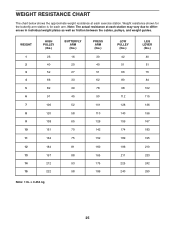
... The actual resistance at each exercise station. WEIGHT 1 2 3 4 5 6 7 8 9 10 11 12 13 14 15 HIGH PULLEY (lbs.) 25 40 52 66 82 91 106 120 138 151 164 184 197 212 222 BUTTERFLY ARM (lbs.) 16 20 27 33 39 45 52 58 65 70 75 81 88 93 98 PRESS ARM (lbs.) ... LEG LEVER (lbs.) 40 51 70 84 102 115 136 156 167 183 195 210 233 242 250 Note: 1 lb. = 0.454 kg 25 WEIGHT RESISTANCE CHART The chart below shows the approximate weight resistance at each station may vary due to differences in individual weight plates as well as friction between the cables, pulleys, and weight guides. Weight resistance ...
... The actual resistance at each exercise station. WEIGHT 1 2 3 4 5 6 7 8 9 10 11 12 13 14 15 HIGH PULLEY (lbs.) 25 40 52 66 82 91 106 120 138 151 164 184 197 212 222 BUTTERFLY ARM (lbs.) 16 20 27 33 39 45 52 58 65 70 75 81 88 93 98 PRESS ARM (lbs.) ... LEG LEVER (lbs.) 40 51 70 84 102 115 136 156 167 183 195 210 233 242 250 Note: 1 lb. = 0.454 kg 25 WEIGHT RESISTANCE CHART The chart below shows the approximate weight resistance at each station may vary due to differences in individual weight plates as well as friction between the cables, pulleys, and weight guides. Weight resistance ...
Uk Manual
Page 27
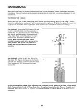
... these cables several ways: See drawing 1. To tighten the cables, first insert the weight pin into the Weight 2 Tube (24) until the slack is felt, the cables should be removed from the Adjustable U- If the cables need to slip off the weight stack. bracket (45), the Cable Trap (51), the 90mm Pulley (48), and the two Half Guards (43). MAINTENANCE Make sure that the Cable and Pulley move smoothly...
... these cables several ways: See drawing 1. To tighten the cables, first insert the weight pin into the Weight 2 Tube (24) until the slack is felt, the cables should be removed from the Adjustable U- If the cables need to slip off the weight stack. bracket (45), the Cable Trap (51), the 90mm Pulley (48), and the two Half Guards (43). MAINTENANCE Make sure that the Cable and Pulley move smoothly...
Uk Manual
Page 28
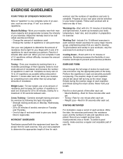
... each set. workout, and the numbers of repetitions or sets performed. Exercise for 20 to your bodyʼs signals. Never hold your body time to complete. Adjust the intensity level of an individual exercise as follows: • Change the amount of resistance used , and the numbers of resistance. When you perform. Write the date, the exercises performed, the resistance used . • Change the number of repetitions and sets to regenerate. Working...
... each set. workout, and the numbers of repetitions or sets performed. Exercise for 20 to your bodyʼs signals. Never hold your body time to complete. Adjust the intensity level of an individual exercise as follows: • Change the amount of resistance used , and the numbers of resistance. When you perform. Write the date, the exercises performed, the resistance used . • Change the number of repetitions and sets to regenerate. Working...
Uk Manual
Page 29
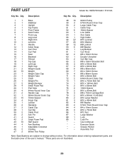
... Bolt 82 4 M6 Washer 83 2 57mm Thick Round Inner Cap 84 4 M4 x 10mm Screw 85 3 M10 x 75mm Bolt 86 1 M12 Nut 87 1 Large Washer 88 1 Lock 89 1 Lock Pin * - Assembly Tool Note: Specifications are not illustrated. 29 For information about ordering replacement parts, see the back cover of the userʼs manual. *These parts are subject to change without notice. Qty. PART LIST Model No. Description Key No. Exercise Guide...
... Bolt 82 4 M6 Washer 83 2 57mm Thick Round Inner Cap 84 4 M4 x 10mm Screw 85 3 M10 x 75mm Bolt 86 1 M12 Nut 87 1 Large Washer 88 1 Lock 89 1 Lock Pin * - Assembly Tool Note: Specifications are not illustrated. 29 For information about ordering replacement parts, see the back cover of the userʼs manual. *These parts are subject to change without notice. Qty. PART LIST Model No. Description Key No. Exercise Guide...
Uk Manual
Page 32
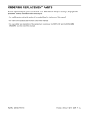
To help us assist you, be prepared to provide the following information when contacting us: • the model number and serial number of the product (see the front cover of this manual) • the name of the product (see the front cover of this manual) • the key number and description of the replacement part(s) (see the front cover of this manual. ORDERING REPLACEMENT PARTS To order replacement parts, please see the PART LIST and the EXPLODED DRAWING near the end of this manual) Part No. 298796 R1010A Printed in China © 2010 ICON IP, Inc.
To help us assist you, be prepared to provide the following information when contacting us: • the model number and serial number of the product (see the front cover of this manual) • the name of the product (see the front cover of this manual) • the key number and description of the replacement part(s) (see the front cover of this manual. ORDERING REPLACEMENT PARTS To order replacement parts, please see the PART LIST and the EXPLODED DRAWING near the end of this manual) Part No. 298796 R1010A Printed in China © 2010 ICON IP, Inc.


