
English Manual
Page 2
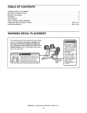
TABLE OF CONTENTS WARNING DECAL PLACEMENT 2 IMPORTANT PRECAUTIONS 3 BEFORE YOU BEGIN 4 ASSEMBLY 5 ADJUSTMENT 6 PART LIST/EXPLODED DRAWING 7 ORDERING REPLACEMENT PARTS Back Cover LIMITED WARRANTY Back Cover WARNING DECAL PLACEMENT This drawing shows the location(s) of ICON IP, Inc. 2 Note: The decal(s) may not be shown at actual size. WEIDER is missing or illegible, see the front cover of this manual and request a free replacement d3e0c9a3l.8A1pply the decal in the location shown. If a decal is a registered trademark of the warning decal(s).
TABLE OF CONTENTS WARNING DECAL PLACEMENT 2 IMPORTANT PRECAUTIONS 3 BEFORE YOU BEGIN 4 ASSEMBLY 5 ADJUSTMENT 6 PART LIST/EXPLODED DRAWING 7 ORDERING REPLACEMENT PARTS Back Cover LIMITED WARRANTY Back Cover WARNING DECAL PLACEMENT This drawing shows the location(s) of ICON IP, Inc. 2 Note: The decal(s) may not be shown at actual size. WEIDER is missing or illegible, see the front cover of this manual and request a free replacement d3e0c9a3l.8A1pply the decal in the location shown. If a decal is a registered trademark of the warning decal(s).

English Manual
Page 5
...way. 6. Make sure that all parts of them. Tighten the two Leveling Feet (5) into the underside of the packing materials until assembly is completed, some extra parts may be left over. Attach the other Tray (9) in the same way. 2. Attach the Tray ...65mm Screws (6). 5. Place a mat beneath the stand to the included tool(s), assembly requires a Phillips screwdriver . Attach the other Weight Plates and Handle. 7. Set six Weight Plates (10, 11, 12) in the same way. 4. Note: After assembly is completed. Do not dispose of the Base (1). 3. In addition to protect ...
...way. 6. Make sure that all parts of them. Tighten the two Leveling Feet (5) into the underside of the packing materials until assembly is completed, some extra parts may be left over. Attach the other Tray (9) in the same way. 2. Attach the Tray ...65mm Screws (6). 5. Place a mat beneath the stand to the included tool(s), assembly requires a Phillips screwdriver . Attach the other Weight Plates and Handle. 7. Set six Weight Plates (10, 11, 12) in the same way. 4. Note: After assembly is completed. Do not dispose of the Base (1). 3. In addition to protect ...
English Manual
Page 7
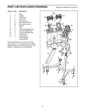
WSAW10011.0 R0411A Key No. Assembly Tool Note: Specifications are not illustrated. 14 13 13 8 11 11 10 12 10 14 13 9 14 9 8 6 13 3 6 7 7 7 2 7 4 4 7 6 7 7 5 7 4 2 4 17 5 7 6 7 For information about ordering ...DRAWING Model No. Description 1 1 Base 2 2 Upright 3 1 Tray Frame 4 4 Base Cap 5 2 Leveling Foot 6 8 M10 x 65mm Screw 7 24 M4 x 20mm Screw 8 2 Handle 9 2 Tray 10 4 2.5-pound Weight Plate 11 4 5-pound Weight Plate 12 4 10-pound Weight Plate 13 4 Handle Cap 14 4 Handle Cover * - Qty. User's Manual * -
WSAW10011.0 R0411A Key No. Assembly Tool Note: Specifications are not illustrated. 14 13 13 8 11 11 10 12 10 14 13 9 14 9 8 6 13 3 6 7 7 7 2 7 4 4 7 6 7 7 5 7 4 2 4 17 5 7 6 7 For information about ordering ...DRAWING Model No. Description 1 1 Base 2 2 Upright 3 1 Tray Frame 4 4 Base Cap 5 2 Leveling Foot 6 8 M10 x 65mm Screw 7 24 M4 x 20mm Screw 8 2 Handle 9 2 Tray 10 4 2.5-pound Weight Plate 11 4 5-pound Weight Plate 12 4 10-pound Weight Plate 13 4 Handle Cap 14 4 Handle Cover * - Qty. User's Manual * -


