
English Manual
Page 2
...TABLE OF CONTENTS LIMITED WARRANTY IMPORTANT PRECAUTIONS BEFORE YOU BEGIN ASSEMBLY HOW TO USE THE HOME GYM SYSTEM WEIGHT RESISTANCE CHART TROUBLE-SHOOTING AND MAINTENANCE CABLE DIAGRAMS ORDERING REPLACEMENT PARTS 2 3 4 5 24 26 27 29 Back Cover Note: A PART IDENTIFICATION CHART and a PART LIST/EXPLODED ... limitation may also have other consequential damages of purchase. ICON HEALTH & FITNESS, INC., 1500 S. 1000 W., LOGAN, UT 84321-9813 2 WEIDER is made must be received by ICON. ICON is authorized by an ICON authorized service center, products used for which vary from the date ...
...TABLE OF CONTENTS LIMITED WARRANTY IMPORTANT PRECAUTIONS BEFORE YOU BEGIN ASSEMBLY HOW TO USE THE HOME GYM SYSTEM WEIGHT RESISTANCE CHART TROUBLE-SHOOTING AND MAINTENANCE CABLE DIAGRAMS ORDERING REPLACEMENT PARTS 2 3 4 5 24 26 27 29 Back Cover Note: A PART IDENTIFICATION CHART and a PART LIST/EXPLODED ... limitation may also have other consequential damages of purchase. ICON HEALTH & FITNESS, INC., 1500 S. 1000 W., LOGAN, UT 84321-9813 2 WEIDER is made must be received by ICON. ICON is authorized by an ICON authorized service center, products used for which vary from the date ...
English Manual
Page 3
...a foot plate when performing an exercise that could become pinched between the leg press upright and the mill- 13 Make sure that the cables remain on thepylleys at any worn parts,immediately. 11. WARNING: Before beginning this manual and in any exercise program, consult your body ... responsibility for foot protection. 3 Read all precautions. 2. Your hand could cause the home gym system to ensure that your physician. If the cables bind while'you feel pain or,dizziness at all ;times. 7. Always disconnect the lat bar from moving parts. Keep your hands away from ...
...a foot plate when performing an exercise that could become pinched between the leg press upright and the mill- 13 Make sure that the cables remain on thepylleys at any worn parts,immediately. 11. WARNING: Before beginning this manual and in any exercise program, consult your body ... responsibility for foot protection. 3 Read all precautions. 2. Your hand could cause the home gym system to ensure that your physician. If the cables bind while'you feel pain or,dizziness at all ;times. 7. Always disconnect the lat bar from moving parts. Keep your hands away from ...
English Manual
Page 5
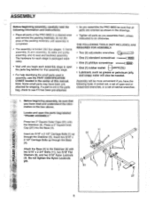
... the following tools: A socket set, a set of open-end or closed-end wrenches, or a set of the PRO 9655 in the box above. Locate and open the parts bag labeled for that all parts are oriented as shown in the ... in the parts bag, check to see if it has been pre-attached. • As you assemble the PRO 9655 be sure that assembly stage. • For help identifying the small parts used in assembly, use the PART IDENTIFICATION...shipping. Press a 2" Square Inner Cap (27) into four stages: 1) frame assembly, 2) arm assembly, 3) cable and pulley assembly, and 4) seat and backrest assembly.
... the following tools: A socket set, a set of open-end or closed-end wrenches, or a set of the PRO 9655 in the box above. Locate and open the parts bag labeled for that all parts are oriented as shown in the ... in the parts bag, check to see if it has been pre-attached. • As you assemble the PRO 9655 be sure that assembly stage. • For help identifying the small parts used in assembly, use the PART IDENTIFICATION...shipping. Press a 2" Square Inner Cap (27) into four stages: 1) frame assembly, 2) arm assembly, 3) cable and pulley assembly, and 4) seat and backrest assembly.
English Manual
Page 11
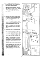
Assemble the other Press Arm (46) in the same manner. Attach a "V"-Pulley (50) and a Long Cable Trap (31) to the Right Arm (48) with the Left Arm (47); Note: Be careful not to one of the Press Arms (46). Wet the ... the Top Frame (55). Do not tighten the Nylon Locknut yet. Press 1 3/4" Square Inner Caps (44) into the Press Arm. Attach a "V"-Pulley (50) and a Long Cable Trap (31) to identify the Right Arm. Tap two 1" Retainers (69) and a 1" Round Cover Cap (70) onto the axle. Press a 1" Round Inner Cap (49) into...
Assemble the other Press Arm (46) in the same manner. Attach a "V"-Pulley (50) and a Long Cable Trap (31) to the Right Arm (48) with the Left Arm (47); Note: Be careful not to one of the Press Arms (46). Wet the ... the Top Frame (55). Do not tighten the Nylon Locknut yet. Press 1 3/4" Square Inner Caps (44) into the Press Arm. Attach a "V"-Pulley (50) and a Long Cable Trap (31) to identify the Right Arm. Tap two 1" Retainers (69) and a 1" Round Cover Cap (70) onto the axle. Press a 1" Round Inner Cap (49) into...
English Manual
Page 13
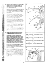
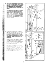
...x 2 3/4" Bolts (11) and two 5/16" Nylon Locknuts (3). Before beginning this manual to the CABLE DIAGRAMS on the Indicated side of each Cable is between the Pulley and the hook. 21 0-0 23-79" 0=10 tr 0 58-142" 0...==Z, z1==a-- 99-64" 22 21 55 58 C 88 Ball 15 Hook 13 IMPORTANT: While assembling the cables, do not overtighten the bolts and nuts attaching the pulleys. Wet the ends of the Left and Right Pull...3 80 79 109 21. The approximate length of the Pulley and that the end of the Cable with soapy water. Attach the Left Pull-up Arm (75) and the Right Pull-up Arms ...
...x 2 3/4" Bolts (11) and two 5/16" Nylon Locknuts (3). Before beginning this manual to the CABLE DIAGRAMS on the Indicated side of each Cable is between the Pulley and the hook. 21 0-0 23-79" 0=10 tr 0 58-142" 0...==Z, z1==a-- 99-64" 22 21 55 58 C 88 Ball 15 Hook 13 IMPORTANT: While assembling the cables, do not overtighten the bolts and nuts attaching the pulleys. Wet the ends of the Left and Right Pull...3 80 79 109 21. The approximate length of the Pulley and that the end of the Cable with soapy water. Attach the Left Pull-up Arm (75) and the Right Pull-up Arms ...
English Manual
Page 14
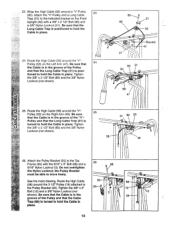
... (31) is positioned to the indicated bracket on the Right Arm (48). Do not overtighten the Nylon Locknut; Route the High Cable (58) around a "V"-Pulley 23 (50). Route the High Cable 55 66 (58) around the "V"Pulley (50) on the Front Upright (42) with the 5/16" x 5" Bolt (68) and ...a 26 68 5/16" Nylon Locknut (3). Attach the "V"-Pulley and a Long Cable Trap (31) to hold the Cable in place. 24. Tighten the 3/8" x 2 1/2" Bolt (86) and the 3/8" Nylon Locknut (not shown). 58 31 86 50 48 26. See the inset...
... (31) is positioned to the indicated bracket on the Right Arm (48). Do not overtighten the Nylon Locknut; Route the High Cable (58) around a "V"-Pulley 23 (50). Route the High Cable 55 66 (58) around the "V"Pulley (50) on the Front Upright (42) with the 5/16" x 5" Bolt (68) and ...a 26 68 5/16" Nylon Locknut (3). Attach the "V"-Pulley and a Long Cable Trap (31) to hold the Cable in place. 24. Tighten the 3/8" x 2 1/2" Bolt (86) and the 3/8" Nylon Locknut (not shown). 58 31 86 50 48 26. See the inset...

English Manual
Page 15
... Pulley (102), with a 3/8" x 2" Bolt (12) and a 3/8" Nylon Locknut (21). Do not tighten the 3/8" Nylon Locknut (21) yet. Attach a 3 1/2" Pulley (15) and a Cable Trap (66) to the upper hole in the groove of the 3 1/2" Low Pulley (102) for part identification. Attach the Pulley to complete the assembly of...3/8" Nylon Locknut (21), the Spacer, and the Pulley from the 3/8" x 3 3/4" Bolt (88). Note: This may come pre-assembled. Route the High Cable (58) through the Long "U"-Bracket (57) and the 3 1/2" Pulley (15) shown in the groove of several pre- 29 attached parts. Note: This ...
... Pulley (102), with a 3/8" x 2" Bolt (12) and a 3/8" Nylon Locknut (21). Do not tighten the 3/8" Nylon Locknut (21) yet. Attach a 3 1/2" Pulley (15) and a Cable Trap (66) to the upper hole in the groove of the 3 1/2" Low Pulley (102) for part identification. Attach the Pulley to complete the assembly of...3/8" Nylon Locknut (21), the Spacer, and the Pulley from the 3/8" x 3 3/4" Bolt (88). Note: This may come pre-assembled. Route the High Cable (58) through the Long "U"-Bracket (57) and the 3 1/2" Pulley (15) shown in the groove of several pre- 29 attached parts. Note: This ...
English Manual
Page 16
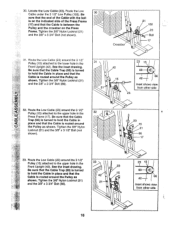
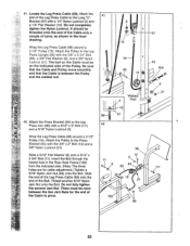
... Locknut (21) and the 3/8" x 3 1/2" Bolt (not shown). 32 23 15 ® 21 66 17 33. Route the Low Cable under the 3 1/2" Low Pulley (102). See the inset drawing. Be sure that the end of the Cable with the ball is on the indicated side of the Press Frame (17) and that the... (66) is turned to the lower hole in place and that the Cable is routed around the Pulley as shown. Route the Low Cable (23) around the 3 1/2" Pulley (15) attached to hold the Cable in the Front Upright (42). Route the Low Cable (23) around the 3 1/2" Pulley (15) attached to the upper hole in...
... Locknut (21) and the 3/8" x 3 1/2" Bolt (not shown). 32 23 15 ® 21 66 17 33. Route the Low Cable under the 3 1/2" Low Pulley (102). See the inset drawing. Be sure that the end of the Cable with the ball is on the indicated side of the Press Frame (17) and that the... (66) is turned to the lower hole in place and that the Cable is routed around the Pulley as shown. Route the Low Cable (23) around the 3 1/2" Pulley (15) attached to hold the Cable in the Front Upright (42). Route the Low Cable (23) around the 3 1/2" Pulley (15) attached to the upper hole in...

English Manual
Page 17
... the Long "U"-Bracket (57) with a 1/4" Nylon 34 Locknut (2) and a 1/4" Flat Washer (10). It should be threaded onto the end of the Cable so only a couple of the Military Press Cable onto 36 72 the other 3/8" x 4" Eyebolt (24). • 24 17 34. Slide the end of threads are showing above the Nylon Locknut..., as shown in the inset drawing. 2- 10 57 23 2 -10 23 57 35. Slide the end of the Low Cable (23) to slide the Cable onto the Eyebolt. 58 71 24 ////L1_1/1/11.//h 36. Attach the end of the High...
... the Long "U"-Bracket (57) with a 1/4" Nylon 34 Locknut (2) and a 1/4" Flat Washer (10). It should be threaded onto the end of the Cable so only a couple of the Military Press Cable onto 36 72 the other 3/8" x 4" Eyebolt (24). • 24 17 34. Slide the end of threads are showing above the Nylon Locknut..., as shown in the inset drawing. 2- 10 57 23 2 -10 23 57 35. Slide the end of the Low Cable (23) to slide the Cable onto the Eyebolt. 58 71 24 ////L1_1/1/11.//h 36. Attach the end of the High...
English Manual
Page 18
... (105) with a 3/8" x 1 3/4" Bolt (76) and a 3/8" Nylon Locknut (21). Be sure that the Cable is between the Pulley and the Assist Arm and that the Long Cable Trap is routed around the Pulley as shown. Attach the Pulley to the Assist Upright (74) with a 3/8" x 2... 1/2" Bolt (86) and a 3/8" Nylon Locknut (21). Wrap the Military Press Cable (72) around a 37 "V"-Pulley (50). 37. Wrap the Military Press Cable (72) around a 3 1/2" Pulley (15). Attach the "V"-Pulley to the Top Frame (55) with a 3/8" x 4 1/2" Bolt (112), a ...
... (105) with a 3/8" x 1 3/4" Bolt (76) and a 3/8" Nylon Locknut (21). Be sure that the Cable is between the Pulley and the Assist Arm and that the Long Cable Trap is routed around the Pulley as shown. Attach the Pulley to the Assist Upright (74) with a 3/8" x 2... 1/2" Bolt (86) and a 3/8" Nylon Locknut (21). Wrap the Military Press Cable (72) around a 37 "V"-Pulley (50). 37. Wrap the Military Press Cable (72) around a 3 1/2" Pulley (15). Attach the "V"-Pulley to the Top Frame (55) with a 3/8" x 4 1/2" Bolt (112), a ...
English Manual
Page 19
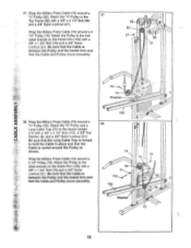
... is positioned to the upper hole in place. 39 21 93 9 9 101 72 15 11 66 88 40. Attach a 3 1/2" Pulley (15) and a Cable Trap (66) to hold the Cable in a Long "U"-Bracket (57) with the 3/8" x 3 3/4" Bolt (88), a 3/8" Flat Washer (9), and a 3/8" Nylon Locknut (21). Slide a 5/16" Flat ...Washer (8) onto a 5/16" x 2 3/4" Bolt (11). Wrap the Military Press Cable (72) around a 3 1/2" Pulley (15). Slide the end of the Military Press Cable (72) onto the end of the Cable to the Pivot Arm (101) with a 3/8" x 2" Bolt (12) and a 3/8" Nylon Locknut (21). Fully ...
... is positioned to the upper hole in place. 39 21 93 9 9 101 72 15 11 66 88 40. Attach a 3 1/2" Pulley (15) and a Cable Trap (66) to hold the Cable in a Long "U"-Bracket (57) with the 3/8" x 3 3/4" Bolt (88), a 3/8" Flat Washer (9), and a 3/8" Nylon Locknut (21). Slide a 5/16" Flat ...Washer (8) onto a 5/16" x 2 3/4" Bolt (11). Wrap the Military Press Cable (72) around a 3 1/2" Pulley (15). Slide the end of the Military Press Cable (72) onto the end of the Cable to the Pivot Arm (101) with a 3/8" x 2" Bolt (12) and a 3/8" Nylon Locknut (21). Fully ...
English Manual
Page 20
... turns, as shown in the Rear Seat Frame (100) from the indicated side. (Note: The three holes are for the end of the Leg Press Cable to pivot. 41 10 • 57 • 99 56 Ball 88 15 .4) Cap - .9 • 21 0 Welded 2 Rod -10 99 57 42 96 O 12 3, 94 99... 111 15 21 O 100 93 20 Slide a 5/16" Flat Washer (8) onto a 5/16" x 2 3/4" Bolt (11). Slide the end of the Leg Press Cable (99) onto the end of the Pulley. Do not fully tighten the second Jam Nut. Insert the Bolt through the lowest hole in the inset...
... turns, as shown in the Rear Seat Frame (100) from the indicated side. (Note: The three holes are for the end of the Leg Press Cable to pivot. 41 10 • 57 • 99 56 Ball 88 15 .4) Cap - .9 • 21 0 Welded 2 Rod -10 99 57 42 96 O 12 3, 94 99... 111 15 21 O 100 93 20 Slide a 5/16" Flat Washer (8) onto a 5/16" x 2 3/4" Bolt (11). Slide the end of the Leg Press Cable (99) onto the end of the Pulley. Do not fully tighten the second Jam Nut. Insert the Bolt through the lowest hole in the inset...
English Manual
Page 23
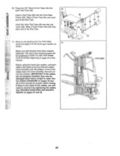
... 51. If there is used. Remove the backing from the PRO 9655 decal and apply it by tightening the cables. IMPORTANT: If the cables are not properly installed, they may be damaged when heavy weight...Tube. The use of the remaining parts will need to remove it to be explained in the cables, you will be sure that all parts have been properly tightened. Press two 3/4" Round Inner Caps...rect the problem. See TROUBLE-SHOOTING AND MAINTE- See the CABLE DIAGRAMS on pages 27 and 28. 36 30 34 28 34 30 0 29 0 PRO 9655 0 0 23 Insert the other Pad Tube (28) into ...
... 51. If there is used. Remove the backing from the PRO 9655 decal and apply it by tightening the cables. IMPORTANT: If the cables are not properly installed, they may be damaged when heavy weight...Tube. The use of the remaining parts will need to remove it to be explained in the cables, you will be sure that all parts have been properly tightened. Press two 3/4" Round Inner Caps...rect the problem. See TROUBLE-SHOOTING AND MAINTE- See the CABLE DIAGRAMS on pages 27 and 28. 36 30 34 28 34 30 0 29 0 PRO 9655 0 0 23 Insert the other Pad Tube (28) into ...
English Manual
Page 24
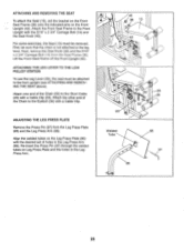
... of the Chain between the Lat Bar and the High Cable so the Lat Bar is in the cables or chain as an exercise is any slack in the correct starting position for each part of 10 pounds. CHANGING THE WEIGHT SETTING The PRO 9655 features two weight stacks. The weight setting of the... Chain between the Lat Bar and the Low Cable so the Lat Bar is in increments of the home gym system can be reduced. Adjust...
... of the Chain between the Lat Bar and the High Cable so the Lat Bar is in the cables or chain as an exercise is any slack in the correct starting position for each part of 10 pounds. CHANGING THE WEIGHT SETTING The PRO 9655 features two weight stacks. The weight setting of the... Chain between the Lat Bar and the Low Cable so the Lat Bar is in increments of the home gym system can be reduced. Adjust...
English Manual
Page 25
...29), the seat must be removed. Align the welded tubes on the Leg Press Plate (95) with a Cable Clip. Re-insert the Press Pin (97) through the welded tubes on the Front Upright (42). For ...Chain to the front upright (see ATTACHING AND REMOVING THE SEAT above). Attach the Front Seat Frame to the Short Cable (23) with the 5/16" x 2 3/4" Carriage Bolt (14) and the Seat Knob (40). ADJUSTING THE... (97) from the Seat Frame (36). Attach one end of the Chain (52) to the Front Upright with a Cable Clip (53). Next, remove the Seat Knob (40) and the 5/16" x 2 3/4" Carriage Bolt (14) from...
...29), the seat must be removed. Align the welded tubes on the Leg Press Plate (95) with a Cable Clip. Re-insert the Press Pin (97) through the welded tubes on the Front Upright (42). For ...Chain to the front upright (see ATTACHING AND REMOVING THE SEAT above). Attach the Front Seat Frame to the Short Cable (23) with the 5/16" x 2 3/4" Carriage Bolt (14) and the Seat Knob (40). ADJUSTING THE... (97) from the Seat Frame (36). Attach one end of the Chain (52) to the Front Upright with a Cable Clip (53). Next, remove the Seat Knob (40) and the 5/16" x 2 3/4" Carriage Bolt (14) from...

English Manual
Page 27
...using a damp cloth and mild non-abrasive detergent. Move the 3 1/2" Pulley (15) to the Long "U"-Bracket (57). Remove the High Cable (58) from the Cable Trap (66), Pulley, and Long "U"-Bracket. Note: You may have to lift the Weight Cover (71) to be adjusted in the same... (24). Loosen the 3/8" 2 Nut (113) on the home gym system, can be tightened. TIGHTENING THE CABLES Woven cable, the type of cable used on the 3/8" x 4" Eyebolt approximately three turns. To tighten the cables, insert the weight pin into the Weight Cover (71) until there is slack in one of the weight...
...using a damp cloth and mild non-abrasive detergent. Move the 3 1/2" Pulley (15) to the Long "U"-Bracket (57). Remove the High Cable (58) from the Cable Trap (66), Pulley, and Long "U"-Bracket. Note: You may have to lift the Weight Cover (71) to be adjusted in the same... (24). Loosen the 3/8" 2 Nut (113) on the home gym system, can be tightened. TIGHTENING THE CABLES Woven cable, the type of cable used on the 3/8" x 4" Eyebolt approximately three turns. To tighten the cables, insert the weight pin into the Weight Cover (71) until there is slack in one of the weight...
English Manual
Page 28
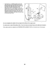
... on the back cover of this manual. 28 If additional slack is felt while using the Leg Press Arm (96), then the end of the Cable, and both 5/16" Nylon Jam Nuts (93) from the Rear Seat Frame. the top weight will be moved to slip off the weight stack. If... to the next hole in the Rear Seat Frame. 96 o 11 8 99 0 93 -J 100 93--. Remove the cable and re-install it may have become twisted. Do not overtighten the cables; If the cables need to the next hole in the Rear Seat Frame (100). Re-attach the Bolt, the Washer, the end...
... on the back cover of this manual. 28 If additional slack is felt while using the Leg Press Arm (96), then the end of the Cable, and both 5/16" Nylon Jam Nuts (93) from the Rear Seat Frame. the top weight will be moved to slip off the weight stack. If... to the next hole in the Rear Seat Frame. 96 o 11 8 99 0 93 -J 100 93--. Remove the cable and re-install it may have become twisted. Do not overtighten the cables; If the cables need to the next hole in the Rear Seat Frame (100). Re-attach the Bolt, the Washer, the end...
English Manual
Page 29
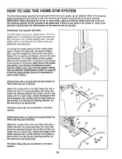
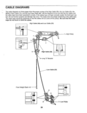
... may occur. Use the diagrams to be positioned so that the cable traps do not touch or bind the cables. High Cable (58) and Low Cable (23) 7 5 2 3 4 6 High Cable (58) 5-Long "U"-Bracket 1 High Pulley Low Cable (23) Front Weight Stack-8 4 0 3 2 1-Low Pulley 29 CABLE DIAGRAMS The cable diagrams on these pages show the proper positioning of the High...
... may occur. Use the diagrams to be positioned so that the cable traps do not touch or bind the cables. High Cable (58) and Low Cable (23) 7 5 2 3 4 6 High Cable (58) 5-Long "U"-Bracket 1 High Pulley Low Cable (23) Front Weight Stack-8 4 0 3 2 1-Low Pulley 29 CABLE DIAGRAMS The cable diagrams on these pages show the proper positioning of the High...

English Manual
Page 30
Military Press Cable (72) and Leg Press Cable (99) 2 Military Press Cable (72) 6 4 Rear Weight Stack-1 3 5 8-Pivot Arm 0 7 1-Long "U"-Bracket 3 2 0 4-Rear Seat Frame Leg Press Cable (99) 30
Military Press Cable (72) and Leg Press Cable (99) 2 Military Press Cable (72) 6 4 Rear Weight Stack-1 3 5 8-Pivot Arm 0 7 1-Long "U"-Bracket 3 2 0 4-Rear Seat Frame Leg Press Cable (99) 30
English Manual
Page 33
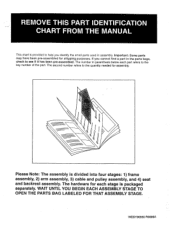
... packaged separately. Important: Some parts may have been pre-assembled for assembly. Please Note: The assembly is divided into four stages: 1) frame assembly, 2) arm assembly, 3) cable and pulley assembly, and 4) seat and backrest assembly. WESY96550 R0996A REMOVE THIS PART IDENTIFICATION CHART FROM THE MANUAL This chart is provided to see if...
... packaged separately. Important: Some parts may have been pre-assembled for assembly. Please Note: The assembly is divided into four stages: 1) frame assembly, 2) arm assembly, 3) cable and pulley assembly, and 4) seat and backrest assembly. WESY96550 R0996A REMOVE THIS PART IDENTIFICATION CHART FROM THE MANUAL This chart is provided to see if...


