
Instruction Manual
Page 1
...1120 To help us assist you complete satisfaction through our Customer Service Department. The SERIAL NUMBER of the product (see the PART LIST and EXPLODED DRAWING attached at the centre of this equipment. Greenwich House 223 North Street Sheepscar West Yorkshire Leeds LS7 ...: ICON Fitness Lifestyle Ltd. The KEY NUMBER and DESCRIPTION of the part(s) (see the front cover of this manual). WESY96450 Serial No. Part No. 141611 R0997A WEIDER is a registered trademark of the product (WEIDER® PRO 9645 Home Gym System). 3. Save this product, contact the ICON Fitness ...
...1120 To help us assist you complete satisfaction through our Customer Service Department. The SERIAL NUMBER of the product (see the PART LIST and EXPLODED DRAWING attached at the centre of this equipment. Greenwich House 223 North Street Sheepscar West Yorkshire Leeds LS7 ...: ICON Fitness Lifestyle Ltd. The KEY NUMBER and DESCRIPTION of the part(s) (see the front cover of this manual). WESY96450 Serial No. Part No. 141611 R0997A WEIDER is a registered trademark of the product (WEIDER® PRO 9645 Home Gym System). 3. Save this product, contact the ICON Fitness ...

Instruction Manual
Page 2
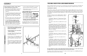
... to ensure that could become pinched between the assist upright and the assist arm. 11. Always disconnect the lat bar from moving parts. Inspect and tighten all cables before kneeling on a foot plate when performing an exercise that all users of the home gym system... all precautions. Make sure that your body weight is being 13. If the cables bind while you feel pain or dizziness at any worn parts immediately. 5. If you are exercising, stop immediately and begin cooling down. Read all of the pulleys. TABLE OF CONTENTS IMPORTANT PRECAUTIONS 2 BEFORE...
... to ensure that could become pinched between the assist upright and the assist arm. 11. Always disconnect the lat bar from moving parts. Inspect and tighten all cables before kneeling on a foot plate when performing an exercise that all users of the home gym system... all precautions. Make sure that your body weight is being 13. If the cables bind while you feel pain or dizziness at any worn parts immediately. 5. If you are exercising, stop immediately and begin cooling down. Read all of the pulleys. TABLE OF CONTENTS IMPORTANT PRECAUTIONS 2 BEFORE...
Instruction Manual
Page 3
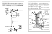
...not touch or bind the cables. Whether your goal is WESY96450. Before reading further, please review the drawing below and familiarise yourself with the parts that the four cables and the cable traps have been assembled correctly. CABLE DIAGRAMS The cable diagrams on a decal attached to be sure that... are labelled. Use the diagrams to the WEIDER® PRO 9645 (see the front cover of the cable traps. The serial number can be found on these pages show the proper positioning of this ...
...not touch or bind the cables. Whether your goal is WESY96450. Before reading further, please review the drawing below and familiarise yourself with the parts that the four cables and the cable traps have been assembled correctly. CABLE DIAGRAMS The cable diagrams on a decal attached to be sure that... are labelled. Use the diagrams to the WEIDER® PRO 9645 (see the front cover of the cable traps. The serial number can be found on these pages show the proper positioning of this ...
Instruction Manual
Page 4
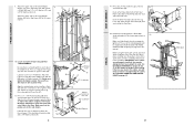
...(57) can stretch slightly when it has been pre-attached. • As you assemble the PRO 9645 be more convenient if you have the following information and instructions: • Place all parts each stage is packaged separately. • Wait until assembly is completed. • The assembly is... Do not tighten the Nylon Locknuts yet. 1 51 51 11 8 5 1 1 3 41 27 4 TROUBLE-SHOOTING AND MAINTENANCE Inspect and tighten all parts of the PRO 9645 in one of the Long "U"-Brackets (57). Insert two 5/16" x 2 1/2" Carriage Bolts up through the Base (4). The home gym system can ...
...(57) can stretch slightly when it has been pre-attached. • As you assemble the PRO 9645 be more convenient if you have the following information and instructions: • Place all parts each stage is packaged separately. • Wait until assembly is completed. • The assembly is... Do not tighten the Nylon Locknuts yet. 1 51 51 11 8 5 1 1 3 41 27 4 TROUBLE-SHOOTING AND MAINTENANCE Inspect and tighten all parts of the PRO 9645 in one of the Long "U"-Brackets (57). Insert two 5/16" x 2 1/2" Carriage Bolts up through the Base (4). The home gym system can ...
Instruction Manual
Page 7
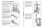
... a Weight Tube Bumper (64) into the 7 end of the holes in a Top Weight (65). Lubricate the inside of resis- CHANGING THE WEIGHT SETTING The PRO 9645 features two weight stacks. Press a Weight Tube Bumper (64) into the end of Weights (25). Set the Top Weight onto the rear stack of either... 52 53 39 54 FRAME ASSEMBLY 7. The weight setting of 12.5 pounds. HOW TO USE THE HOME GYM SYSTEM The instructions below describe how each part of Weights. The Nylon Strap (39) can be adjusted.
... a Weight Tube Bumper (64) into the 7 end of the holes in a Top Weight (65). Lubricate the inside of resis- CHANGING THE WEIGHT SETTING The PRO 9645 features two weight stacks. Press a Weight Tube Bumper (64) into the end of Weights (25). Set the Top Weight onto the rear stack of either... 52 53 39 54 FRAME ASSEMBLY 7. The weight setting of 12.5 pounds. HOW TO USE THE HOME GYM SYSTEM The instructions below describe how each part of Weights. The Nylon Strap (39) can be adjusted.
Instruction Manual
Page 8
...Square Inner Cap (27) into each Pad Tube (28). The Leg Press Arm must be sure that all parts have been properly tightened. Align the welded tubes on pages 26 and 27 of the Pad Tube. 48..... Before using the home gym system, pull each welded spacer on page 25. 36 30 34 28 34 30 29 PRO 9645 21 If there is used. Insert a Pad Tube (28) into the Leg Lever (29). Lubricate the 3/8" x 8"...to the Top Frame (55) with one of the Stabiliser (5). Remove the backing from the PRO 9645 48 decal and apply it by tightening the cables. Make sure that the pulleys are not properly ...
...Square Inner Cap (27) into each Pad Tube (28). The Leg Press Arm must be sure that all parts have been properly tightened. Align the welded tubes on pages 26 and 27 of the Pad Tube. 48..... Before using the home gym system, pull each welded spacer on page 25. 36 30 34 28 34 30 29 PRO 9645 21 If there is used. Insert a Pad Tube (28) into the Leg Lever (29). Lubricate the 3/8" x 8"...to the Top Frame (55) with one of the Stabiliser (5). Remove the backing from the PRO 9645 48 decal and apply it by tightening the cables. Make sure that the pulleys are not properly ...
Instruction Manual
Page 10
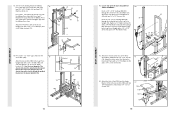
... Assist Arm must also be attached to the Leg Press Upright with a 3/8" x 6" Bolt (106), two 3/8" Flat Washers (9), and a 3/8" Nylon Locknut (21). Locate and open the parts bag labelled 40 "SEAT ASSEMBLY." See the inset drawing. The Assist Arm must be below the welded bracket on the Assist Upright (74). 33 101...
... Assist Arm must also be attached to the Leg Press Upright with a 3/8" x 6" Bolt (106), two 3/8" Flat Washers (9), and a 3/8" Nylon Locknut (21). Locate and open the parts bag labelled 40 "SEAT ASSEMBLY." See the inset drawing. The Assist Arm must be below the welded bracket on the Assist Upright (74). 33 101...
Instruction Manual
Page 11
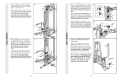
... Pull-up Arm (77) to the CABLE DIAGRAMS on the indicated side of the Pulley. Wet the end of the Bolt. Locate and open the parts bags labelled "CABLE ASSEMBLY" and "PULLEYS." 18 During steps 19 through the lowest hole in the same manner. It should be able to pivot. Locate...
... Pull-up Arm (77) to the CABLE DIAGRAMS on the indicated side of the Pulley. Wet the end of the Bolt. Locate and open the parts bags labelled "CABLE ASSEMBLY" and "PULLEYS." 18 During steps 19 through the lowest hole in the same manner. It should be able to pivot. Locate...
Instruction Manual
Page 13
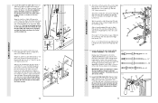
... is inside the Long "U"Bracket. Attach the "V"-Pulley and a Long Cable Trap (31) to the upper hole in the groove of several pre- 26 attached parts. Attach a 3 1/2" Pulley (15) and a Cable Trap (66) to the Assist Upright (74) with a 3/8" x 2 1/2" Bolt (86) and a 3/8" Nylon Locknut (21). Note...High Cable (58) through the Long "U"-Bracket (57) and the 3 1/2" Pulley (15) shown in the groove of the 3 1/2" Low Pulley (102) for part identification. Be sure that the Cable is in the inset drawing. Attach the Pulley to the bracket on the Assist Arm (105) with a 3/8" x 1 3/4" Bolt...
... is inside the Long "U"Bracket. Attach the "V"-Pulley and a Long Cable Trap (31) to the upper hole in the groove of several pre- 26 attached parts. Attach a 3 1/2" Pulley (15) and a Cable Trap (66) to the Assist Upright (74) with a 3/8" x 2 1/2" Bolt (86) and a 3/8" Nylon Locknut (21). Note...High Cable (58) through the Long "U"-Bracket (57) and the 3 1/2" Pulley (15) shown in the groove of the 3 1/2" Low Pulley (102) for part identification. Be sure that the Cable is in the inset drawing. Attach the Pulley to the bracket on the Assist Arm (105) with a 3/8" x 1 3/4" Bolt...
Instruction Manual
Page 15
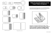
...stage is packaged separately. WESY96450 R0996A Important: Some parts may have been pre-assembled for each part refers to the key number of the part. If you identify the small parts used in assembly. WAIT UNTIL YOU BEGIN EACH ASSEMBLY STAGE TO OPEN THE PARTS BAG LABELLED FOR THAT ASSEMBLY STAGE. The hardware... backrest assembly. 5/8" x 9/16" Spacer (7)-1 1/2" x 3/4" Spacer (61)-4 5/16" x 2" Eyebolt (35)-1 3/4" Round Inner Cap (34)-4 1" Round Inner Cap (49)-6 1" Round Cover Cap (70)-2 REMOVE THIS PART IDENTIFICATION CHART FROM THE MANUAL This chart is provided to help you cannot find...
...stage is packaged separately. WESY96450 R0996A Important: Some parts may have been pre-assembled for each part refers to the key number of the part. If you identify the small parts used in assembly. WAIT UNTIL YOU BEGIN EACH ASSEMBLY STAGE TO OPEN THE PARTS BAG LABELLED FOR THAT ASSEMBLY STAGE. The hardware... backrest assembly. 5/8" x 9/16" Spacer (7)-1 1/2" x 3/4" Spacer (61)-4 5/16" x 2" Eyebolt (35)-1 3/4" Round Inner Cap (34)-4 1" Round Inner Cap (49)-6 1" Round Cover Cap (70)-2 REMOVE THIS PART IDENTIFICATION CHART FROM THE MANUAL This chart is provided to help you cannot find...
Instruction Manual
Page 17
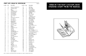
... Seat Assist Arm 3/8" x 6" Bolt 1" x 2" Inner Cap Short Weight Tube 1 1/4" Round Inner Cap Angle Bracket 5/16" x 3" Bolt 3/8" x 4 1/2" Bolt Short Handgrip User's Manual Note: "#" indicates a non-illustrated part. PART LIST-Model No. Qty. 1 10 2 6 3 36 4 1 5 1 6 1 7 1 8 9 9 9 10 15 11 14 12 5 13 2 14 1 15 13 16 1 17 1 18 6 19 4 20 1 21 23 22 4 ... Top Frame Leg Press Upright Long "U"-Bracket Key No. Specifications are subject to change without notice. WESY96450 R0996A Key No. REMOVE THIS PART LIST/EXPLODED DRAWING CHART FROM THE MANUAL 81
... Seat Assist Arm 3/8" x 6" Bolt 1" x 2" Inner Cap Short Weight Tube 1 1/4" Round Inner Cap Angle Bracket 5/16" x 3" Bolt 3/8" x 4 1/2" Bolt Short Handgrip User's Manual Note: "#" indicates a non-illustrated part. PART LIST-Model No. Qty. 1 10 2 6 3 36 4 1 5 1 6 1 7 1 8 9 9 9 10 15 11 14 12 5 13 2 14 1 15 13 16 1 17 1 18 6 19 4 20 1 21 23 22 4 ... Top Frame Leg Press Upright Long "U"-Bracket Key No. Specifications are subject to change without notice. WESY96450 R0996A Key No. REMOVE THIS PART LIST/EXPLODED DRAWING CHART FROM THE MANUAL 81


