
Instruction Manual
Page 1
The MODEL NUMBER of the product (WEIDER® PRO 9645 Home Gym System). 3. If you complete satisfaction through our Customer Service Department. Save this manual for reference. The SERIAL NUMBER of the product (see the PART LIST and EXPLODED DRAWING attached at the centre of this manual). 4. Write the serial number in USA Model No. Serial Number Decal (Under Seat) QUESTIONS? The NAME of the product (WESY96450). 2. Part No. 141611 R0997A WEIDER is a registered...
The MODEL NUMBER of the product (WEIDER® PRO 9645 Home Gym System). 3. If you complete satisfaction through our Customer Service Department. Save this manual for reference. The SERIAL NUMBER of the product (see the PART LIST and EXPLODED DRAWING attached at the centre of this manual). 4. Write the serial number in USA Model No. Serial Number Decal (Under Seat) QUESTIONS? The NAME of the product (WESY96450). 2. Part No. 141611 R0997A WEIDER is a registered...

Instruction Manual
Page 2
... from the home gym system at all instructions in this or any worn parts immediately. 5. Read all times. 6. Always wear athletic shoes for protection. 4. Use the home gym system only on the assist arm. TABLE OF CONTENTS IMPORTANT PRECAUTIONS 2 BEFORE YOU BEGIN 3 ASSEMBLY 4 HOW TO USE THE HOME GYM SYSTEM 22 WEIGHT RESISTANCE CHART 24 TROUBLE-SHOOTING AND MAINTENANCE 25 CABLE DIAGRAMS 26 ORDERING REPLACEMENT PARTS Back Cover Note: A PART IDENTIFICATION CHART and a PART LIST/EXPLODED...
... from the home gym system at all instructions in this or any worn parts immediately. 5. Read all times. 6. Always wear athletic shoes for protection. 4. Use the home gym system only on the assist arm. TABLE OF CONTENTS IMPORTANT PRECAUTIONS 2 BEFORE YOU BEGIN 3 ASSEMBLY 4 HOW TO USE THE HOME GYM SYSTEM 22 WEIGHT RESISTANCE CHART 24 TROUBLE-SHOOTING AND MAINTENANCE 25 CABLE DIAGRAMS 26 ORDERING REPLACEMENT PARTS Back Cover Note: A PART IDENTIFICATION CHART and a PART LIST/EXPLODED...
Instruction Manual
Page 3
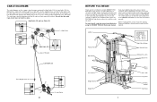
... every major muscle group of the body. If you for selecting the versatile WEIDER® PRO 9645 Home Gym System. The serial number can be positioned so that the four cables and the cable traps have not been correctly routed, the home gym system will not come off the pulleys. CABLE DIAGRAMS The cable diagrams on a decal attached to the WEIDER® PRO 9645 (see the front cover of this manual carefully before calling.
... every major muscle group of the body. If you for selecting the versatile WEIDER® PRO 9645 Home Gym System. The serial number can be positioned so that the four cables and the cable traps have not been correctly routed, the home gym system will not come off the pulleys. CABLE DIAGRAMS The cable diagrams on a decal attached to the WEIDER® PRO 9645 (see the front cover of this manual carefully before calling.
Instruction Manual
Page 4
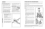
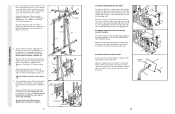
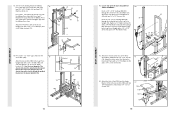
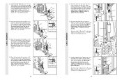
... assembly. To tighten the cables, insert the weight pin into the Base (4). Move the 3 1/2" Pulley (15) to the next hole in the centre of this manual. The other hole in the Rear Seat Frame (100). Remove the 5/16" x 2 3/4" Bolt (11), the 5/16" Washer (8), the end of the Long "U"-Brackets (57). Before beginning assembly, be sure that connects the end of the Leg Press Cable (99) must be needed. Press...
... assembly. To tighten the cables, insert the weight pin into the Base (4). Move the 3 1/2" Pulley (15) to the next hole in the centre of this manual. The other hole in the Rear Seat Frame (100). Remove the 5/16" x 2 3/4" Bolt (11), the 5/16" Washer (8), the end of the Long "U"-Brackets (57). Before beginning assembly, be sure that connects the end of the Leg Press Cable (99) must be needed. Press...
Instruction Manual
Page 5
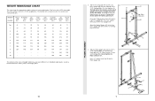
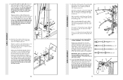
... 5/16" x 2 1/2" Carriage Bolts (1) in the Base (4). 3 Hand-tighten a 5/16" Nylon Locknut (3) onto each butterfly arm. Do not tighten the Nylon Locknuts yet. Press a 2" Square Inner Cap into the Leg Press Upright (56). WEIGHT RESISTANCE CHART This chart shows the approximate weight resistance at each weight station may vary due to differences in individual weight plates, as well as friction between the cables, pulleys, and weight guides. 24 FRAME ASSEMBLY 2. Press two 2" Square...
... 5/16" x 2 1/2" Carriage Bolts (1) in the Base (4). 3 Hand-tighten a 5/16" Nylon Locknut (3) onto each butterfly arm. Do not tighten the Nylon Locknuts yet. Press a 2" Square Inner Cap into the Leg Press Upright (56). WEIGHT RESISTANCE CHART This chart shows the approximate weight resistance at each weight station may vary due to differences in individual weight plates, as well as friction between the cables, pulleys, and weight guides. 24 FRAME ASSEMBLY 2. Press two 2" Square...
Instruction Manual
Page 6
... the Press Pin (97) through the welded tubes on the same side of each end of Weights. Attach the Top Frame (55) to the Assist Upright (74) and the Leg Press Upright (56) with a Cable Clip. Next, remove the Seat Knob (40) and the 5/16" x 2 3/4" Carriage Bolt (14) from the Leg Press Plate (95) and the Leg Press Arm (96). Attach one end of the Chain to the Rear Seat Frame...
... the Press Pin (97) through the welded tubes on the same side of each end of Weights. Attach the Top Frame (55) to the Assist Upright (74) and the Leg Press Upright (56) with a Cable Clip. Next, remove the Seat Knob (40) and the 5/16" x 2 3/4" Carriage Bolt (14) from the Leg Press Plate (95) and the Leg Press Arm (96). Attach one end of the Chain to the Rear Seat Frame...
Instruction Manual
Page 7
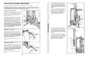
... assist arm, and leg press. To change the weight setting of resistance at the top, as an exercise is in the correct starting position for the exercise to 106.5 pounds, in the top Weight. Note: Due to the cables and pulleys, the amount of either weight stack can be changed from the weight setting. Use the WEIGHT RESISTANCE CHART on the Weight Tube is sitting in the pin grooves in increments of the home gym...
... assist arm, and leg press. To change the weight setting of resistance at the top, as an exercise is in the correct starting position for the exercise to 106.5 pounds, in the top Weight. Note: Due to the cables and pulleys, the amount of either weight stack can be changed from the weight setting. Use the WEIGHT RESISTANCE CHART on the Weight Tube is sitting in the pin grooves in increments of the home gym...
Instruction Manual
Page 8
... overtighten the Nylon Locknut. The Leg Press Arm must be explained in HOW TO USE THE HOME GYM SYSTEM, beginning on this manual. Slide the Press Frame into the Front Seat Frame (36). Slide a Foam Foam Pad (30) onto each Pad Tube (28). If one set of the cables does not move smoothly over the pulleys. Lubricate the 3/8" x 8" Bolt (59). Attach the Press Frame (17) to be...
... overtighten the Nylon Locknut. The Leg Press Arm must be explained in HOW TO USE THE HOME GYM SYSTEM, beginning on this manual. Slide the Press Frame into the Front Seat Frame (36). Slide a Foam Foam Pad (30) onto each Pad Tube (28). If one set of the cables does not move smoothly over the pulleys. Lubricate the 3/8" x 8" Bolt (59). Attach the Press Frame (17) to be...
Instruction Manual
Page 9
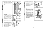
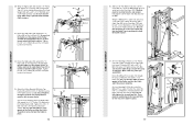
... 31 50 47 21 Attach a "V"-Pulley (50) and a Long Cable Trap (31) to the Front Seat Frame (36) with a 5/16" x 2 3/4" Carriage Bolt (14) and the Seat Knob (40). Be sure that 48 the teeth on the Top Frame (55). SEAT ASSEMBLY ARM ASSEMBLY 43. Lubricate the 5/16" x 2 1/4" Bolt (33). Press 1 3/4" Square Inner Caps (44) into the Leg Lever (29). Wet the lower end of the Right...
... 31 50 47 21 Attach a "V"-Pulley (50) and a Long Cable Trap (31) to the Front Seat Frame (36) with a 5/16" x 2 3/4" Carriage Bolt (14) and the Seat Knob (40). Be sure that 48 the teeth on the Top Frame (55). SEAT ASSEMBLY ARM ASSEMBLY 43. Lubricate the 5/16" x 2 1/4" Bolt (33). Press 1 3/4" Square Inner Caps (44) into the Leg Lever (29). Wet the lower end of the Right...
Instruction Manual
Page 10
... Handgrips (83) onto the Military Press Arm. See the inset drawing. Locate and open the parts bag labelled 40 "SEAT ASSEMBLY." Tighten a 1/4" Nylon Locknut (2) with two 1/4" x 1/2" Screws 41 (18). Attach one end of the Rear Backrest (85) to the Pivot Arm (101) with two 1/4" x 1/2" Screws (18). 56 Insert the 1/4" x 2 1/2" Carriage Bolt (92) through the centre hole in the Leg Press Upright (56). Press two 1" Round Inner Caps (49...
... Handgrips (83) onto the Military Press Arm. See the inset drawing. Locate and open the parts bag labelled 40 "SEAT ASSEMBLY." Tighten a 1/4" Nylon Locknut (2) with two 1/4" x 1/2" Screws 41 (18). Attach one end of the Rear Backrest (85) to the Pivot Arm (101) with two 1/4" x 1/2" Screws (18). 56 Insert the 1/4" x 2 1/2" Carriage Bolt (92) through the centre hole in the Leg Press Upright (56). Press two 1" Round Inner Caps (49...
Instruction Manual
Page 11
... Inner Caps (109) into the Left Pull-up Arm (77). IMPORTANT: While assembling the cables, do not overtighten the bolts and nuts attaching the pulleys. Wet the end of the Leg Press Cable to turn freely. 19 19. Before beginning this manual to pivot. Locate the High Cable (58). Attach the Pulley to the Assist Upright (74) with the 3/8" x 2" Bolt (12) and a 3/8" Nylon Locknut (21). Slide a 5/16...
... Inner Caps (109) into the Left Pull-up Arm (77). IMPORTANT: While assembling the cables, do not overtighten the bolts and nuts attaching the pulleys. Wet the end of the Leg Press Cable to turn freely. 19 19. Before beginning this manual to pivot. Locate the High Cable (58). Attach the Pulley to the Assist Upright (74) with the 3/8" x 2" Bolt (12) and a 3/8" Nylon Locknut (21). Slide a 5/16...
Instruction Manual
Page 12
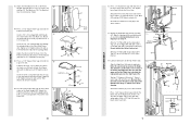
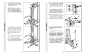
... come preassembled.) Route the Military Press Cable (72) through the indicated hole in place. Fully tighten a 5/16" Nylon Jam Nut (93) onto the Bolt. Attach the Pulley and a Cable Trap (66) to the Top 23 Frame (55) with the 3/8" x 3 3/4" Bolt (88), a 3/8" Flat Washer (9), and a 3/8" Nylon Locknut (21). CABLE ASSEMBLY CABLE ASSEMBLY 20. Route the High Cable (58) around a "V"-Pulley 20 (50). Tighten the 3/8" x 2" 20 12 Bolt (12) and...
... come preassembled.) Route the Military Press Cable (72) through the indicated hole in place. Fully tighten a 5/16" Nylon Jam Nut (93) onto the Bolt. Attach the Pulley and a Cable Trap (66) to the Top 23 Frame (55) with the 3/8" x 3 3/4" Bolt (88), a 3/8" Flat Washer (9), and a 3/8" Nylon Locknut (21). CABLE ASSEMBLY CABLE ASSEMBLY 20. Route the High Cable (58) around a "V"-Pulley 20 (50). Tighten the 3/8" x 2" 20 12 Bolt (12) and...
Instruction Manual
Page 13
... Press Cable (72) around a "V"-Pulley (50). Note: This assembly step shows how to hold the Cable in the groove of the Pulley and that the Cable and Pulley move smoothly. 25. Attach the "V"-Pulley and a Long Cable Trap (31) to the other bracket on the outside of several pre- 26 attached parts. Be sure that the Long Cable Trap is routed around a 3 1/2" Pulley (15). Attach the Pulley to the Assist Upright...
... Press Cable (72) around a "V"-Pulley (50). Note: This assembly step shows how to hold the Cable in the groove of the Pulley and that the Cable and Pulley move smoothly. 25. Attach the "V"-Pulley and a Long Cable Trap (31) to the other bracket on the outside of several pre- 26 attached parts. Be sure that the Long Cable Trap is routed around a 3 1/2" Pulley (15). Attach the Pulley to the Assist Upright...
Instruction Manual
Page 14
... the Front Upright (42). It should be threaded onto the end of the Cable only a couple of the Press Frame (17) and that the Cable is routed around the Pulley as shown. Tighten the 3/8" Nylon Locknut (21) and the 3/8" x 3 3/4" Bolt (not shown). See the inset drawing. Do not completely tighten the Nylon Locknut. Attach the High Cable (58) to the lower hole...
... the Front Upright (42). It should be threaded onto the end of the Cable only a couple of the Press Frame (17) and that the Cable is routed around the Pulley as shown. Tighten the 3/8" Nylon Locknut (21) and the 3/8" x 3 3/4" Bolt (not shown). See the inset drawing. Do not completely tighten the Nylon Locknut. Attach the High Cable (58) to the lower hole...
Instruction Manual
Page 15
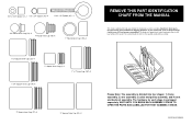
... (51)-2 Please Note: The assembly is divided into four stages: 1) frame assembly, 2) arm assembly, 3) cable and pulley assembly, and 4) seat and backrest assembly. 5/8" x 9/16" Spacer (7)-1 1/2" x 3/4" Spacer (61)-4 5/16" x 2" Eyebolt (35)-1 3/4" Round Inner Cap (34)-4 1" Round Inner Cap (49)-6 1" Round Cover Cap (70)-2 REMOVE THIS PART IDENTIFICATION CHART FROM THE MANUAL This chart is provided to help you cannot find a part in assembly. The number in parenthesis below each...
... (51)-2 Please Note: The assembly is divided into four stages: 1) frame assembly, 2) arm assembly, 3) cable and pulley assembly, and 4) seat and backrest assembly. 5/8" x 9/16" Spacer (7)-1 1/2" x 3/4" Spacer (61)-4 5/16" x 2" Eyebolt (35)-1 3/4" Round Inner Cap (34)-4 1" Round Inner Cap (49)-6 1" Round Cover Cap (70)-2 REMOVE THIS PART IDENTIFICATION CHART FROM THE MANUAL This chart is provided to help you cannot find a part in assembly. The number in parenthesis below each...
Instruction Manual
Page 16
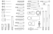
... Flat Washer (9)-9 1/4" x 2" Machine Screw (81)-1 1/4" x 2 1/2" Carriage Bolt (92)-1 5/16" x 2 1/2" Bolt (22)-4 3/8" x 2" Bolt (12)-5 5/16" x 2 1/4" Bolt (33)-3 1/4" x 2 1/2" Screw (43)-8 5/16" x 2 1/2" Carriage Bolt (1)-10 3/8" x 2 1/2" Bolt (86)-4 5/16" x 2 3/4" Bolt (11)-14 5/16" x 2 3/4" Carriage Bolt (14)-1 3/8" x 3 1/4" Bolt (67)-2 3/8" x 3 1/2" Bolt (16)-1 3/8" x 3 3/4" Bolt (88)-6 5/16" x 5" Bolt (68)-1 5/16" x 3" Bolt (111)-1 1/4" x 1/2" Screw (18)-6 Cable Clip (53)-3 1" Retainer (69)-4 1 1/8" x 2 1/2" Plastic Bushing (89)-2 1" x 7/8" Plastic Bushing (90)-2 3 1/2" Pulley (15)-13...
... Flat Washer (9)-9 1/4" x 2" Machine Screw (81)-1 1/4" x 2 1/2" Carriage Bolt (92)-1 5/16" x 2 1/2" Bolt (22)-4 3/8" x 2" Bolt (12)-5 5/16" x 2 1/4" Bolt (33)-3 1/4" x 2 1/2" Screw (43)-8 5/16" x 2 1/2" Carriage Bolt (1)-10 3/8" x 2 1/2" Bolt (86)-4 5/16" x 2 3/4" Bolt (11)-14 5/16" x 2 3/4" Carriage Bolt (14)-1 3/8" x 3 1/4" Bolt (67)-2 3/8" x 3 1/2" Bolt (16)-1 3/8" x 3 3/4" Bolt (88)-6 5/16" x 5" Bolt (68)-1 5/16" x 3" Bolt (111)-1 1/4" x 1/2" Screw (18)-6 Cable Clip (53)-3 1" Retainer (69)-4 1 1/8" x 2 1/2" Plastic Bushing (89)-2 1" x 7/8" Plastic Bushing (90)-2 3 1/2" Pulley (15)-13...
Instruction Manual
Page 17
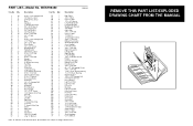
...Bracket Military Press Cable Short Weight Guide Assist Upright Left Pull-up Arm 3/8" x 1 3/4" Bolt Right Pull-up Arm Left Dip Arm Right Dip Arm Long Handgrip 1/4" x 2" Machine Screw Handle 5" Plastic Handgrip Military Press Arm Rear Backrest 3/8" x 2 1/2" Bolt #8 x 1/2" Self-tapping Screw 3/8" x 3 3/4" Bolt 1 1/8" x 2 1/2" Plastic Bushing 1" x 7/8" Plastic Bushing Rubber Bumper 1/4" x 2 1/2" Carriage Bolt 5/16" Nylon Jam Nut Press Bracket Leg Press Plate Leg Press Arm Press Pin Bushing Leg Press Cable Rear Seat Frame Pivot Arm 3 1/2" Low Pulley Handle Cap Assist Seat Assist Arm 3/8" x 6" Bolt...
...Bracket Military Press Cable Short Weight Guide Assist Upright Left Pull-up Arm 3/8" x 1 3/4" Bolt Right Pull-up Arm Left Dip Arm Right Dip Arm Long Handgrip 1/4" x 2" Machine Screw Handle 5" Plastic Handgrip Military Press Arm Rear Backrest 3/8" x 2 1/2" Bolt #8 x 1/2" Self-tapping Screw 3/8" x 3 3/4" Bolt 1 1/8" x 2 1/2" Plastic Bushing 1" x 7/8" Plastic Bushing Rubber Bumper 1/4" x 2 1/2" Carriage Bolt 5/16" Nylon Jam Nut Press Bracket Leg Press Plate Leg Press Arm Press Pin Bushing Leg Press Cable Rear Seat Frame Pivot Arm 3 1/2" Low Pulley Handle Cap Assist Seat Assist Arm 3/8" x 6" Bolt...
Instruction Manual
Page 18
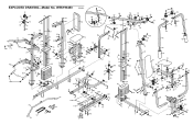
... 54 39 110 105 15 76 3 4 10 3 15 17 66 102 7 23 53 52 83 43 10 43 1 27 21 21 59 90 EXPLODED DRAWING-Model No.
... 54 39 110 105 15 76 3 4 10 3 15 17 66 102 7 23 53 52 83 43 10 43 1 27 21 21 59 90 EXPLODED DRAWING-Model No.


