
English Manual
Page 2
TABLE OF CONTENTS IMPORTANT PRECAUTIONS 3 BEFORE YOU BEGIN 4 ASSEMBLY 5 ADJUSTMENTS 14 WEIGHT RESISTANCE CHART 16 TROUBLESHOOTING AND MAINTENANCE 17 CABLE DIAGRAM 18 ORDERING REPLACEMENT PARTS Back Cover LIMITED WARRANTY Back Cover Note: A PART IDENTIFICATION CHART and a PART LIST/EXPLODED DRAWING are attached to the center of this manual. Remove the PART IDENTIFICATION CHART and PART LIST/EXPLODED DRAWING before beginning assembly. 2
TABLE OF CONTENTS IMPORTANT PRECAUTIONS 3 BEFORE YOU BEGIN 4 ASSEMBLY 5 ADJUSTMENTS 14 WEIGHT RESISTANCE CHART 16 TROUBLESHOOTING AND MAINTENANCE 17 CABLE DIAGRAM 18 ORDERING REPLACEMENT PARTS Back Cover LIMITED WARRANTY Back Cover Note: A PART IDENTIFICATION CHART and a PART LIST/EXPLODED DRAWING are attached to the center of this manual. Remove the PART IDENTIFICATION CHART and PART LIST/EXPLODED DRAWING before beginning assembly. 2
English Manual
Page 4
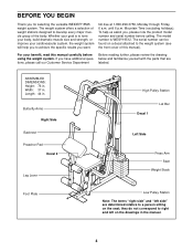
To help you to right and left side" are labeled. ASSEMBLED DIMENSIONS: Height: 76 in . Length: 44 in . they do not correspond to achieve the specific results you have additional questions, please call our Customer Service ... number and serial number before using the weight system. Whether your cardiovascular system, the weight system will help us assist you for selecting the versatile WEIDER® 8525 weight system.
To help you to right and left side" are labeled. ASSEMBLED DIMENSIONS: Height: 76 in . Length: 44 in . they do not correspond to achieve the specific results you have additional questions, please call our Customer Service ... number and serial number before using the weight system. Whether your cardiovascular system, the weight system will help us assist you for selecting the versatile WEIDER® 8525 weight system.
English Manual
Page 5
...is important to ensure that by anyone. Press a 2" Square Inner 27 Cap (27) into the end of the Base (4) to do otherwise. • As you assemble them, unless instructed to the Stabilizer (5) with two 5/16" x 2 3/4" Carriage Bolts (14) and two 5/16" Nylon Locknuts (3). Insert two 5/16" x ...convenient if you have a socket set, a set of open-end or closed-end wrenches, or a set of the Stabilizer (5). Assembly will go smoothly. • Assembly requires two people. • Place all parts are required for Yourself Everything in this manual. Press two 2" Square Outer Caps (...
...is important to ensure that by anyone. Press a 2" Square Inner 27 Cap (27) into the end of the Base (4) to do otherwise. • As you assemble them, unless instructed to the Stabilizer (5) with two 5/16" x 2 3/4" Carriage Bolts (14) and two 5/16" Nylon Locknuts (3). Insert two 5/16" x ...convenient if you have a socket set, a set of open-end or closed-end wrenches, or a set of the Stabilizer (5). Assembly will go smoothly. • Assembly requires two people. • Place all parts are required for Yourself Everything in this manual. Press two 2" Square Outer Caps (...
English Manual
Page 7
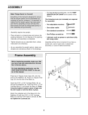
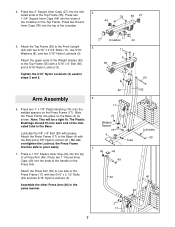
..." x 2 3/4" Bolts (11), two 5/16" Washers (8), and two 5/16" Nylon Locknuts (3). Press two 2" Square Inner Caps (27) into the ends of a Press Arm (46). Arm Assembly 6. Note: This will be able to the Base (4) with two 5/16" x 2 1/2" Bolts (22) and two 5/16" Nylon Locknuts (3). Attach the Press Frame (17) to pivot...) into the top of the handle on the Top Frame. Press a 1 3/4" Square Inner Cap (44) into the top of the crossbar on the Press Arm. Assemble the other Press Arm (46) in the same manner. 27 Crossbar 5 11 8 55 3 42 6 17 44 8 3 60 62 21 Welded Spacer 75 4 Tube 7...
..." x 2 3/4" Bolts (11), two 5/16" Washers (8), and two 5/16" Nylon Locknuts (3). Press two 2" Square Inner Caps (27) into the ends of a Press Arm (46). Arm Assembly 6. Note: This will be able to the Base (4) with two 5/16" x 2 1/2" Bolts (22) and two 5/16" Nylon Locknuts (3). Attach the Press Frame (17) to pivot...) into the top of the handle on the Top Frame. Press a 1 3/4" Square Inner Cap (44) into the top of the crossbar on the Press Arm. Assemble the other Press Arm (46) in the same manner. 27 Crossbar 5 11 8 55 3 42 6 17 44 8 3 60 62 21 Welded Spacer 75 4 Tube 7...
English Manual
Page 8
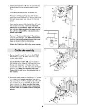
... the ball is routed around a 3 1/2" Pulley 10 (15). Attach the Pulley and a Cable Trap (66) to hold the Cable in the same manner. 70 Cable Assembly 9. Make sure that the Cable is on page 18 of the Cable with a 3/8" x 3 3/4" Bolt (71), a 3/8" Washer (9), and a 3/8" Nylon Locknut (21). Locate the Short Cable (58...
... the ball is routed around a 3 1/2" Pulley 10 (15). Attach the Pulley and a Cable Trap (66) to hold the Cable in the same manner. 70 Cable Assembly 9. Make sure that the Cable is on page 18 of the Cable with a 3/8" x 3 3/4" Bolt (71), a 3/8" Washer (9), and a 3/8" Nylon Locknut (21). Locate the Short Cable (58...
English Manual
Page 11
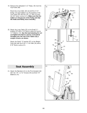
... Small "U"-bracket (67) to the Small "U"- 20 bracket (67) with the 5/16" x 1 3/4" Bolt (72) and a 3 67 5/16" Nylon Locknut (3). 72 10 63 2 23 2 67 Seat Assembly 21 21.
... Small "U"-bracket (67) to the Small "U"- 20 bracket (67) with the 5/16" x 1 3/4" Bolt (72) and a 3 67 5/16" Nylon Locknut (3). 72 10 63 2 23 2 67 Seat Assembly 21 21.

English Manual
Page 12
... (35) into the Seat Frame (36). 22. Attach the other Pad Tube (28) to the Front Upright with a 1/4" Washer (10) and the 1/4" x 2" Screw (24). 23. Assemble the other end of a 12 1/2" Pad Tube (28). Press a 1 1/2" Square Inner Cap (32) into the Seat Frame (36). Attach the Seat Frame to the Leg...
... (35) into the Seat Frame (36). 22. Attach the other Pad Tube (28) to the Front Upright with a 1/4" Washer (10) and the 1/4" x 2" Screw (24). 23. Assemble the other end of a 12 1/2" Pad Tube (28). Press a 1 1/2" Square Inner Cap (32) into the Seat Frame (36). Attach the Seat Frame to the Leg...
English Manual
Page 18
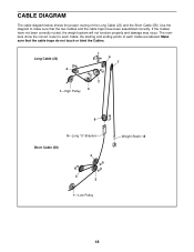
... touch or bind the Cables. Long Cable (23) 4 5 7 2 3 1-High Pulley 6 5-Long "U"-Bracket Short Cable (58) 4 3 2 1-Low Pulley Weight Stack-8 18 If the Cables have been assembled correctly. CABLE DIAGRAM The cable diagram below shows the proper routing of each Cable; the starting and ending points of the Long Cable (23) and...
... touch or bind the Cables. Long Cable (23) 4 5 7 2 3 1-High Pulley 6 5-Long "U"-Bracket Short Cable (58) 4 3 2 1-Low Pulley Weight Stack-8 18 If the Cables have been assembled correctly. CABLE DIAGRAM The cable diagram below shows the proper routing of each Cable; the starting and ending points of the Long Cable (23) and...


