

User Manual
Page 2
TABLE OF CONTENTS LIMITED WARRANTY IMPORTANT PRECAUTIONS BEFORE YOU BEGIN ASSEMBLY HOW TO USE THE HOME GYM SYSTEM TROUBLESHOOTING AND MAINTENANCE CABLE DIAGRAM ORDERING REPLACEMENT PARTS 2 3 4 5 15 18 19 Back Cover Note: A PART IDENTIFICATION CHART and a ... pre-authorized by sufficient proof of whatsoever nature. This warranty gives you . Remove the PART IDENTIFICATION CHART and the PART LIST/EXPLODED DRAWING before beginning assembly. This warranty does not extend to any economic loss, loss of property, loss of revenues or profits, loss of enjoyment or use, costs of removal...
TABLE OF CONTENTS LIMITED WARRANTY IMPORTANT PRECAUTIONS BEFORE YOU BEGIN ASSEMBLY HOW TO USE THE HOME GYM SYSTEM TROUBLESHOOTING AND MAINTENANCE CABLE DIAGRAM ORDERING REPLACEMENT PARTS 2 3 4 5 15 18 19 Back Cover Note: A PART IDENTIFICATION CHART and a ... pre-authorized by sufficient proof of whatsoever nature. This warranty gives you . Remove the PART IDENTIFICATION CHART and the PART LIST/EXPLODED DRAWING before beginning assembly. This warranty does not extend to any economic loss, loss of property, loss of revenues or profits, loss of enjoyment or use, costs of removal...
User Manual
Page 4
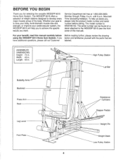
...found on a decal attached to tone your body, build dramatic muscle size and strength, or improve your cardiovascular system, the WEIDER® 8515 will help us assist you want. Whether your benefit, read this manual). For your goal is WESY85150. High Pulley Station Lat... and familiarize yourself with the parts that are have additional questions, please call our Customer labeled. ASSEMBLED DIMENSIONS: Height: 74 in. Mountain Time (excluding holidays). The WEIDER® 8515 offers a selection of weight stations designed to achieve the specific results you , please note the ...
...found on a decal attached to tone your body, build dramatic muscle size and strength, or improve your cardiovascular system, the WEIDER® 8515 will help us assist you want. Whether your benefit, read this manual). For your goal is WESY85150. High Pulley Station Lat... and familiarize yourself with the parts that are have additional questions, please call our Customer labeled. ASSEMBLED DIMENSIONS: Height: 74 in. Mountain Time (excluding holidays). The WEIDER® 8515 offers a selection of weight stations designed to achieve the specific results you , please note the ...
User Manual
Page 5
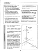
...) onto the Carriage Bolts. Slide a Hand Grip (31) onto each Carriage Bolt. Press a 2" Square Outer Cap (51) onto each assembly stage to do not dispose of the packing materials until you assemble the WEIDER 8515, be needed. Note: Some small parts may have the following information and instructions: • Place all parts as grease...
...) onto the Carriage Bolts. Slide a Hand Grip (31) onto each Carriage Bolt. Press a 2" Square Outer Cap (51) onto each assembly stage to do not dispose of the packing materials until you assemble the WEIDER 8515, be needed. Note: Some small parts may have the following information and instructions: • Place all parts as grease...

User Manual
Page 6
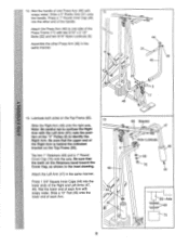
... • 3 5 -J CD 1 4 Slot 1 Press a 2" Square Inner Cap (27) into the end 1.11 2 of the crossbar. Press two 1" Round Inner Caps (49) into each Carriage Bolt. Assemble the Right Pedal (not shown) in the Stabilizer (5). Hand-tighten a 5/16" Nylon Locknut (3) onto each end of the crossbar on the Top Frame. Press a 1" Square...
... • 3 5 -J CD 1 4 Slot 1 Press a 2" Square Inner Cap (27) into the end 1.11 2 of the crossbar. Press two 1" Round Inner Caps (49) into each Carriage Bolt. Assemble the Right Pedal (not shown) in the Stabilizer (5). Hand-tighten a 5/16" Nylon Locknut (3) onto each end of the crossbar on the Top Frame. Press a 1" Square...
User Manual
Page 9
... indicated bracket on the Top Frame (55). Press a 1" Round Inner Cap (49) into the lower ends of the Press Frame (17) with 12 soapy water. Assemble the other end of the handle. note the posi- Be sure that the teeth on the Top Frame (55). 12. Be sure that the upper...
... indicated bracket on the Top Frame (55). Press a 1" Round Inner Cap (49) into the lower ends of the Press Frame (17) with 12 soapy water. Assemble the other end of the handle. note the posi- Be sure that the teeth on the Top Frame (55). 12. Be sure that the upper...
User Manual
Page 10
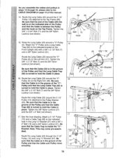
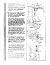
... Cable Trap (66) to hold the Cable in place. Be sure that the Cable Trap (66) is inside the "U"Bracket. Note: This may come pre-assembled. Attach the "V"-Pulley and a Long Cable Trap (50) to hold the Cable in place. Route the Long Cable (23) around the "V"Pulley (6) on... the groove of the Pulley and that the Cable is turned to the indicated bracket on the Top Frame. See the inset drawing. As you assemble the cables and pulleys in steps 14 through the 3 1/2" Pulley (15) and Long "U"-Bracket (57). Tighten the 3/8" x 2 1/2" Bolt (7) and the 3/8" Nylon Locknut (not...
... Cable Trap (66) to hold the Cable in place. Be sure that the Cable Trap (66) is inside the "U"Bracket. Note: This may come pre-assembled. Attach the "V"-Pulley and a Long Cable Trap (50) to hold the Cable in place. Route the Long Cable (23) around the "V"Pulley (6) on... the groove of the Pulley and that the Cable is turned to the indicated bracket on the Top Frame. See the inset drawing. As you assemble the cables and pulleys in steps 14 through the 3 1/2" Pulley (15) and Long "U"-Bracket (57). Tighten the 3/8" x 2 1/2" Bolt (7) and the 3/8" Nylon Locknut (not...
User Manual
Page 11
... upper hole in the "3 o'clock" position and that the Cable Trap (66) is in the Front Upright (42). Be sure that the Cable is pre-assembled. Do not completely tighten the Nylon Locknut.
... upper hole in the "3 o'clock" position and that the Cable Trap (66) is in the Front Upright (42). Be sure that the Cable is pre-assembled. Do not completely tighten the Nylon Locknut.
User Manual
Page 19
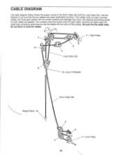
... of the Short Cable (58) and the Long Cable (23). The starting and ending points for each cable are labeled. If the cables have been assembled correctly. Examine all cable traps; the cable traps should be sure that the cables will not function properly and damage may occur. The numbers show...
... of the Short Cable (58) and the Long Cable (23). The starting and ending points for each cable are labeled. If the cables have been assembled correctly. Examine all cable traps; the cable traps should be sure that the cables will not function properly and damage may occur. The numbers show...


