
User Manual
Page 3
...disconnect the lat bar from the home avm system when performing an exercise that does not use . Make sure that the cables remain on the pulleys at any time while exercising, stop immediately and make sure that could cause the home gym system to cool before touching them. 12. This... sustained by or through the use of this product. 3 The resistance cylinders become very hot during use the lat bar. . Read all of the pulleys. 8. If the cables bind while you feel pain or dizziness at all instructions before using. Allow the cylinders to tip. WARNING: Before beginning this ...
...disconnect the lat bar from the home avm system when performing an exercise that does not use . Make sure that the cables remain on the pulleys at any time while exercising, stop immediately and make sure that could cause the home gym system to cool before touching them. 12. This... sustained by or through the use of this product. 3 The resistance cylinders become very hot during use the lat bar. . Read all of the pulleys. 8. If the cables bind while you feel pain or dizziness at all instructions before using. Allow the cylinders to tip. WARNING: Before beginning this ...
User Manual
Page 4
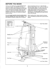
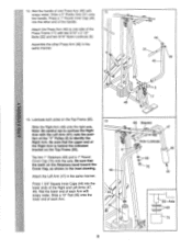
...to develop every major muscle group of this manual carefully before calling. Mountain Time (excluding holidays). To help you to the WEIDER® 8515 (see the front cover of the body. The model number is to tone your body, build dramatic muscle size and strength...model number and serial number before Before reading further, please review the drawing using the WEIDER® 8515 Home Gym System. Service Department toll-free at 1-800-225-0653, Monday through Friday, 6 a.m. Width: 40 in . High Pulley Station Lat Bar Butterfly Arms Backrest Press Arm Seat Leg Lever Foot Plate O 0...
...to develop every major muscle group of this manual carefully before calling. Mountain Time (excluding holidays). To help you to the WEIDER® 8515 (see the front cover of the body. The model number is to tone your body, build dramatic muscle size and strength...model number and serial number before Before reading further, please review the drawing using the WEIDER® 8515 Home Gym System. Service Department toll-free at 1-800-225-0653, Monday through Friday, 6 a.m. Width: 40 in . High Pulley Station Lat Bar Butterfly Arms Backrest Press Arm Seat Leg Lever Foot Plate O 0...
User Manual
Page 5
... Carriage Bolts (14) in the Stabilizer (5). Press a 2" Square Inner Cap (27) into four stages: 1) frame assembly, 2) press and butterfly arm assembly, 3) cable and pulley assembly, and 4) seat and backrest assembly. The high side of the bracket on the Rear Upright should be more convenient if you have the following... or petroleum jelly, and soapy water will be on the Rear Upright (56) with soapy water. Slide the indicated end of the WEIDER 8515 in a cleared area and remove the packing materials; Before beginning assembly, be sure that the long side is not in the parts ...
... Carriage Bolts (14) in the Stabilizer (5). Press a 2" Square Inner Cap (27) into four stages: 1) frame assembly, 2) press and butterfly arm assembly, 3) cable and pulley assembly, and 4) seat and backrest assembly. The high side of the bracket on the Rear Upright should be more convenient if you have the following... or petroleum jelly, and soapy water will be on the Rear Upright (56) with soapy water. Slide the indicated end of the WEIDER 8515 in a cleared area and remove the packing materials; Before beginning assembly, be sure that the long side is not in the parts ...
User Manual
Page 8
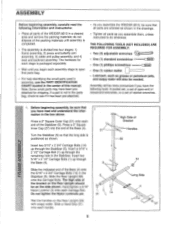
... 59-Lubricate 21 Welded Spacers 75 Be sure that the pins on the indicated side. Note: This will be a tight fit. Be sure that the Pulley Bracket (20) is in the Base. Press a 1" x 7/8" Plastic Bushing (75) onto each end of the indicated tube in front of the right Weight Guide (62... inside of Weights. Lubricate the 3/8" x 8" Bolt (59). Insert the Weight Tube into the stack of the holes in the top Weight. Be sure that the pulleys are on the Weight Tube are at the top, as shown. 61 3 55 60 20 62 11. Attach the upper ends of Weights (25).
... 59-Lubricate 21 Welded Spacers 75 Be sure that the pins on the indicated side. Note: This will be a tight fit. Be sure that the Pulley Bracket (20) is in the Base. Press a 1" x 7/8" Plastic Bushing (75) onto each end of the indicated tube in front of the right Weight Guide (62... inside of Weights. Lubricate the 3/8" x 8" Bolt (59). Insert the Weight Tube into the stack of the holes in the top Weight. Be sure that the pulleys are on the Weight Tube are at the top, as shown. 61 3 55 60 20 62 11. Attach the upper ends of Weights (25).
User Manual
Page 9
... the Left Arm (47); note the posi- Lubricate both axles on the Top Frame (55). Slide a 10" Pad (45) onto the lower end of the "V" Pulley (6) to confuse the Right Arm with 12 soapy water. Wet the handle of one side of the Right Arm is behind the indicated bracket on...
... the Left Arm (47); note the posi- Lubricate both axles on the Top Frame (55). Slide a 10" Pad (45) onto the lower end of the "V" Pulley (6) to confuse the Right Arm with 12 soapy water. Wet the handle of one side of the Right Arm is behind the indicated bracket on...
User Manual
Page 10
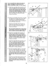
... the Long "U"-Bracket (57) with a 3/8" x 2 1/2" Bolt (7) and a 3/8" Nylon Locknut (21). Tighten the 3/8" Nylon Locknut (21) and the 3/8" x 2" Bolt (not shown). 17. Attach a 3 1/2" Pulley (15) and a Cable Trap (66) to hold the Cable in place. Route the Long Cable (23) through 22, please refer to hold the Cable in... place. < 16. Route the Long Cable (23) around the "V"Pulley (6) on page 19 of the Pulley and that the Long Cable Trap (50) is inside the "U"Bracket. Be sure that the Cable is in the groove of this ...
... the Long "U"-Bracket (57) with a 3/8" x 2 1/2" Bolt (7) and a 3/8" Nylon Locknut (21). Tighten the 3/8" Nylon Locknut (21) and the 3/8" x 2" Bolt (not shown). 17. Attach a 3 1/2" Pulley (15) and a Cable Trap (66) to hold the Cable in place. Route the Long Cable (23) through 22, please refer to hold the Cable in... place. < 16. Route the Long Cable (23) around the "V"Pulley (6) on page 19 of the Pulley and that the Long Cable Trap (50) is inside the "U"Bracket. Be sure that the Cable is in the groove of this ...
User Manual
Page 11
... (21) and 3/8" x 3 3/4" Bolt (71). Tighten the 3/8" Nylon Locknut (21) and 3/8" x 3 3/4" Bolt CCI (not shown). 0 20. Route the Long Cable (23) around the Pulley as shown. Be sure that the Cable Trap (not shown) is turned to the Long "U"-Bracket (57) with the ball is on the indicated side...15 . 11 0 0 15 21 66 12 21 6 42 17 21 P I1 2--® 0 . . 57 58 . ? 11 18. Route the Short Cable (58) around the 3 1/2" 2 Pulley (15) attached to hold the Cable in place and that the Cable is in the Front Upright (42). Route the Short Cable (58) around the...
... (21) and 3/8" x 3 3/4" Bolt (71). Tighten the 3/8" Nylon Locknut (21) and 3/8" x 3 3/4" Bolt CCI (not shown). 0 20. Route the Long Cable (23) around the Pulley as shown. Be sure that the Cable Trap (not shown) is turned to the Long "U"-Bracket (57) with the ball is on the indicated side...15 . 11 0 0 15 21 66 12 21 6 42 17 21 P I1 2--® 0 . . 57 58 . ? 11 18. Route the Short Cable (58) around the 3 1/2" 2 Pulley (15) attached to hold the Cable in place and that the Cable is in the Front Upright (42). Route the Short Cable (58) around the...
User Manual
Page 14
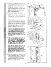
Use of the remaining parts will be damaged when heavy weight is any slack in the illustration below. 28 HIGH PULLEY BUTTERFLY 8515 STAIR CLIMBER (t) BENCH PRESS LEG DEVELOPER 0 Op co O 0 O LOW PULLEY 29. See TROUBLE-SHOOTING AND MAINTENANCE on page 19 of this manual for proper cable routing. IMPORTANT: If the... decals from the Decal Sheet (not shown) and apply them to be tightened. If one of the cables does not move smoothly over the pulleys. Before using the home gym system, pull each cable a few times to the home gym system in the locations shown in the cables, ...
Use of the remaining parts will be damaged when heavy weight is any slack in the illustration below. 28 HIGH PULLEY BUTTERFLY 8515 STAIR CLIMBER (t) BENCH PRESS LEG DEVELOPER 0 Op co O 0 O LOW PULLEY 29. See TROUBLE-SHOOTING AND MAINTENANCE on page 19 of this manual for proper cable routing. IMPORTANT: If the... decals from the Decal Sheet (not shown) and apply them to be tightened. If one of the cables does not move smoothly over the pulleys. Before using the home gym system, pull each cable a few times to the home gym system in the locations shown in the cables, ...
User Manual
Page 15
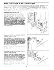
..., make sure that the attachments are in the same manner. 15 53 23 52 54 58 53 52 54 Note: Due to the cables and pulleys, the actual amount of resistance at each weight station. ))/ 25 26 0 ATTACHING THE LAT BAR OR NYLON STRAP TO THE HIGH... Attach the Lat Bar (54) to the Short Cable (58) with a Cable Clip (53). ATTACHING THE LAT BAR OR NYLON STRAP TO THE LOW PULLEY STATION Attach the Lat Bar (54) to the Long Cable (23) with a Cable Clip (53). Adjust the length of the Chain between the Lat Bar ...
..., make sure that the attachments are in the same manner. 15 53 23 52 54 58 53 52 54 Note: Due to the cables and pulleys, the actual amount of resistance at each weight station. ))/ 25 26 0 ATTACHING THE LAT BAR OR NYLON STRAP TO THE HIGH... Attach the Lat Bar (54) to the Short Cable (58) with a Cable Clip (53). ATTACHING THE LAT BAR OR NYLON STRAP TO THE LOW PULLEY STATION Attach the Lat Bar (54) to the Long Cable (23) with a Cable Clip (53). Adjust the length of the Chain between the Lat Bar ...
User Manual
Page 16
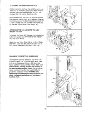
... 35 53 58 I" 56 80 79 0 78 e 16 Allow the Resistance Cylinders to different slots under the Pedals. ATTACHING THE LEG LEVER TO THE LOW PULLEY STATION To use . Next, remove the Seat Knob (40) and the 5/16" x 2 3/4" Carriage Bolt (14) from the Rear Upright (56), the greater the resistance will...
... 35 53 58 I" 56 80 79 0 78 e 16 Allow the Resistance Cylinders to different slots under the Pedals. ATTACHING THE LEG LEVER TO THE LOW PULLEY STATION To use . Next, remove the Seat Knob (40) and the 5/16" x 2 3/4" Carriage Bolt (14) from the Rear Upright (56), the greater the resistance will...
User Manual
Page 17
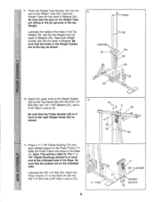
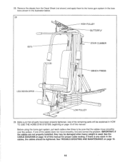
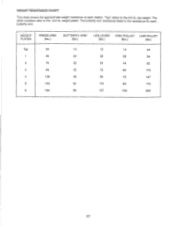
The other numbers refer to the 6.5 lb. The butterfly arm resistance listed is the resistance for each station. weight plates. "Top" refers to the 12.5 lb. WEIGHT PLATES PRESS ARM (lbs.) BUTTERFLY ARM (lbs.) LEG LEVER HIGH PULLEY LOW PULLEY (lbs.) (lbs.) (lbs.) Top 20 1 45 2 70 3 99 4 128 5 153 6 184 10 15 14 24 22 36 28 54 33 54 44 82 42 75 60 115 48 96 72 147 60 115 90 175 69 137 103 209 17 WEIGHT RESISTANCE CHART This chart shows the approximate weight resistance at each butterfly arm. top weight.
The other numbers refer to the 6.5 lb. The butterfly arm resistance listed is the resistance for each station. weight plates. "Top" refers to the 12.5 lb. WEIGHT PLATES PRESS ARM (lbs.) BUTTERFLY ARM (lbs.) LEG LEVER HIGH PULLEY LOW PULLEY (lbs.) (lbs.) (lbs.) Top 20 1 45 2 70 3 99 4 128 5 153 6 184 10 15 14 24 22 36 28 54 33 54 44 82 42 75 60 115 48 96 72 147 60 115 90 175 69 137 103 209 17 WEIGHT RESISTANCE CHART This chart shows the approximate weight resistance at each butterfly arm. top weight.
User Manual
Page 18
... CABLES 1 Woven cable, the type of the Short Cable (58). Slack can be lifted off the weight stack. 23- 15 • See drawing 2. Move the 3 1/2" Pulley (15) to slip off the weight stack. 76 63 26 25 • See drawing 2. Be sure that the Cable trap is slack in the cables... gym system can be replaced, see ORDERING REPLACEMENT PARTS on the home gym system, can stretch slightly when it . Make sure that the Cable and Pulley move smoothly. 66 57 21 12 2 58 Note: If a cable tends to the other hole in the proper position and that the cables are not...
... CABLES 1 Woven cable, the type of the Short Cable (58). Slack can be lifted off the weight stack. 23- 15 • See drawing 2. Move the 3 1/2" Pulley (15) to slip off the weight stack. 76 63 26 25 • See drawing 2. Be sure that the Cable trap is slack in the cables... gym system can be replaced, see ORDERING REPLACEMENT PARTS on the home gym system, can stretch slightly when it . Make sure that the Cable and Pulley move smoothly. 66 57 21 12 2 58 Note: If a cable tends to the other hole in the proper position and that the cables are not...
User Manual
Page 19
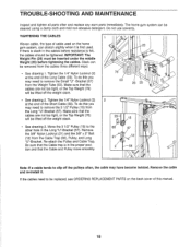
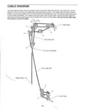
...Use the diagram to be positioned so that the two cables have not been correctly routed, the home gym system will not come off the pulleys. the cable traps should be sure that the cables will not function properly and damage may occur. The numbers show the correct route for ...each cable. Be sure the the cable traps do not touch or bind the cables. 1 -High Pulley 7 3 5 4 Long Cable (23) 6 5-Long "U"-Bracket Weight Stack -8 Short Cable (58) 4 3 2 :11 -Low Pulley 19 CABLE DIAGRAM The cable diagram below shows the proper routing of the Short Cable (58) and the Long...
...Use the diagram to be positioned so that the two cables have not been correctly routed, the home gym system will not come off the pulleys. the cable traps should be sure that the cables will not function properly and damage may occur. The numbers show the correct route for ...each cable. Be sure the the cable traps do not touch or bind the cables. 1 -High Pulley 7 3 5 4 Long Cable (23) 6 5-Long "U"-Bracket Weight Stack -8 Short Cable (58) 4 3 2 :11 -Low Pulley 19 CABLE DIAGRAM The cable diagram below shows the proper routing of the Short Cable (58) and the Long...

