

English Manual
Page 1
... to providing complete custiAner satisfaction. Model No. The trained technicians on our customer hot line will guarantee you . CUSTOMER HOT LINE: 1-800-999-3756 C Mon.-Fri., 6 a.m.-6 p.m. TO AVOID UNNECESSARY DELAYS, PLEASE CALL DIRECT TO OUR TOLL-FREE CUSTOMER HOT LINE. WEBE35560 Serial No. PATENT PENDING USER'S MANUAL Serial Number Decal QUESTIONS? Write the serial number in the space above for future •...
... to providing complete custiAner satisfaction. Model No. The trained technicians on our customer hot line will guarantee you . CUSTOMER HOT LINE: 1-800-999-3756 C Mon.-Fri., 6 a.m.-6 p.m. TO AVOID UNNECESSARY DELAYS, PLEASE CALL DIRECT TO OUR TOLL-FREE CUSTOMER HOT LINE. WEBE35560 Serial No. PATENT PENDING USER'S MANUAL Serial Number Decal QUESTIONS? Write the serial number in the space above for future •...

English Manual
Page 2
... purchaser. The warranty extended hereunder is in connection with the use , costs of removal, installation or other consequential damages of purchase. This warranty gives you specific legal rights. TABLE OF CONTENTS LIMITED WARRANTY IMPORTANT PRECAUTIONS BEFORE YOU BEGIN PART IDENTIFICATION CHART ASSEMBLY ADJUSTING THE WEIDER PRO 355 EXERCISE GUIDELINES PART LIST EXPLODED DRAWING ORDERING REPLACEMENT PARTS 2 3 4 5 6 12 14 18 19 Back Cover LIMITED WARRANTY ICON Health & Fitness, Inc. (ICON), warrants this warranty is limited to replacing or repairing, at ICON's option, the...
... purchaser. The warranty extended hereunder is in connection with the use , costs of removal, installation or other consequential damages of purchase. This warranty gives you specific legal rights. TABLE OF CONTENTS LIMITED WARRANTY IMPORTANT PRECAUTIONS BEFORE YOU BEGIN PART IDENTIFICATION CHART ASSEMBLY ADJUSTING THE WEIDER PRO 355 EXERCISE GUIDELINES PART LIST EXPLODED DRAWING ORDERING REPLACEMENT PARTS 2 3 4 5 6 12 14 18 19 Back Cover LIMITED WARRANTY ICON Health & Fitness, Inc. (ICON), warrants this warranty is limited to replacing or repairing, at ICON's option, the...

English Manual
Page 3
... owner to support a maximum of 510 pounds, including the user, a weight bar and weights. Inspect and tighten all parts each time you are a quately informed of all instructions in this or any exercise program, consult your physician. Always wear athletic;shoes for hPrkle:0 only 000 weight :bench ,in this product oAkm,a,,ottit.. Wnen.;usmg:the 400190st:11144e spre: that ;150 pounds•on the leg...
... owner to support a maximum of 510 pounds, including the user, a weight bar and weights. Inspect and tighten all parts each time you are a quately informed of all instructions in this or any exercise program, consult your physician. Always wear athletic;shoes for hPrkle:0 only 000 weight :bench ,in this product oAkm,a,,ottit.. Wnen.;usmg:the 400190st:11144e spre: that ;150 pounds•on the leg...

English Manual
Page 4
... Low Pulley Station High'Pulley Station Lat Bar Adjustment Holes Backrest Seat 0 0 0 Leg Lever Weight Tube The versatile PRO 355 Weight Bench is designed to be found on a decal attached to the WEIDER' PRO 355 Weight Bench (see the front cover of the body. Whether your goal is WEBE35560. Service Department toll-free at the drawing below and familiarize yourself with your benefit, read this manual). If you for selecting the WEIDER° PRO 355 Weight Bench. The model number...
... Low Pulley Station High'Pulley Station Lat Bar Adjustment Holes Backrest Seat 0 0 0 Leg Lever Weight Tube The versatile PRO 355 Weight Bench is designed to be found on a decal attached to the WEIDER' PRO 355 Weight Bench (see the front cover of the body. Whether your goal is WEBE35560. Service Department toll-free at the drawing below and familiarize yourself with your benefit, read this manual). If you for selecting the WEIDER° PRO 355 Weight Bench. The model number...

English Manual
Page 5
... Screw (5)-2 M6 x 36mm Screw (6)-4 M6 x 60mm Carriage Bolt (14)-1 M8 x 60mm Carriage Bolt (3)-10 0 M10 Washer (10)-2 \\\\\\\\ M8 x 68mm Bolt (8)-10 \\\\\\\\ M10 x 89mm Bolt (9)-2 M10 x 120mm Bolt (12)-1 M10 x 43mm Bolt (11)-1 M10 x 72mm Bolt (1)-1 Important: Some parts may have been pre-assembled for assembly. If you identify the small parts used in assembly. The number in the parts bags, check to the key number of the part. PART IDENTIFICATION CHART This chart...
... Screw (5)-2 M6 x 36mm Screw (6)-4 M6 x 60mm Carriage Bolt (14)-1 M8 x 60mm Carriage Bolt (3)-10 0 M10 Washer (10)-2 \\\\\\\\ M8 x 68mm Bolt (8)-10 \\\\\\\\ M10 x 89mm Bolt (9)-2 M10 x 120mm Bolt (12)-1 M10 x 43mm Bolt (11)-1 M10 x 72mm Bolt (1)-1 Important: Some parts may have been pre-assembled for assembly. If you identify the small parts used in assembly. The number in the parts bags, check to the key number of the part. PART IDENTIFICATION CHART This chart...

English Manual
Page 6
... pre-attached. • Tighten all parts are facing the floor. Be sure that you have been pre-attached for shipping purposes. Note: Some small parts may have the following information and instructions:_ _ • Place all parts of the WEIDER® PRO 355 in the Carriage Stop with the "U" Bracket (30), two M8 x 68mm Bolts (8), and two M8 Nylon Locknuts (4). Before beginning assembly, be needed. Assembly will...
... pre-attached. • Tighten all parts are facing the floor. Be sure that you have been pre-attached for shipping purposes. Note: Some small parts may have the following information and instructions:_ _ • Place all parts of the WEIDER® PRO 355 in the Carriage Stop with the "U" Bracket (30), two M8 x 68mm Bolts (8), and two M8 Nylon Locknuts (4). Before beginning assembly, be needed. Assembly will...
English Manual
Page 7
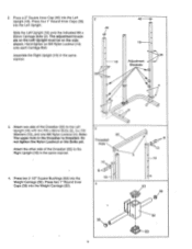
... the indicated M8 x 60mm Carriage Bolts (3). The adjustment brackets on the Left Upright must be on the side shown. Hand-tighten an M8 Nylon Locknut (13) onto each Carriage Bolt. Assemble the Right Upright (19) in the same manner. 4. Note: The upper hole in the Crossbar is ) O O 52 53 2. Attach one M8 Nylon Locknut (4). Press two 2 1/2" Square Bushings (53...
... the indicated M8 x 60mm Carriage Bolts (3). The adjustment brackets on the Left Upright must be on the side shown. Hand-tighten an M8 Nylon Locknut (13) onto each Carriage Bolt. Assemble the Right Upright (19) in the same manner. 4. Note: The upper hole in the Crossbar is ) O O 52 53 2. Attach one M8 Nylon Locknut (4). Press two 2 1/2" Square Bushings (53...
English Manual
Page 8
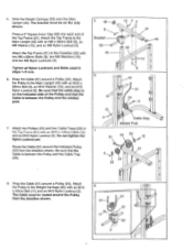
... the welded post. 7. Wrap the Cable (51) around a Pulley (24). Attach the Pulley to the Crossbar (22) with two M8 x 68mm Bolts (8), two M8 Washers (13), and two M8 Nylon Locknuts (4). Wrap the Cable (51) around a Pulley (24). Attach the. Tighten all Nylon Locknuts and Bolts used in steps 1-5 now. 6. Slide the Weight Carriage (52) onto the Main Upright (42). The bracket must be...
... the welded post. 7. Wrap the Cable (51) around a Pulley (24). Attach the Pulley to the Crossbar (22) with two M8 x 68mm Bolts (8), two M8 Washers (13), and two M8 Nylon Locknuts (4). Wrap the Cable (51) around a Pulley (24). Attach the. Tighten all Nylon Locknuts and Bolts used in steps 1-5 now. 6. Slide the Weight Carriage (52) onto the Main Upright (42). The bracket must be...
English Manual
Page 9
.... Press a 2" Square Inner Cap (46) into each Carriage Bolt. Slide the end of the Stabilizer (33). Wrap the Cable (51) around the indicated Pulley (24). Be sure that the cable stop is between the Pulley and the welded post. 11. Insert two M8 x 60mm Carriage Bolts (3) up through the Bench Base (43). 12. Route the Cable (51) around a Pulley (24). Attach the Pulley to...
.... Press a 2" Square Inner Cap (46) into each Carriage Bolt. Slide the end of the Stabilizer (33). Wrap the Cable (51) around the indicated Pulley (24). Be sure that the cable stop is between the Pulley and the welded post. 11. Insert two M8 x 60mm Carriage Bolts (3) up through the Bench Base (43). 12. Route the Cable (51) around a Pulley (24). Attach the Pulley to...

English Manual
Page 10
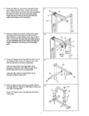
... Lubricate the M10 x 72mm Bolt (1). Attach the Adjustment Backrest Bracket (26) to the Bench Frame (49) with two MG x 36r-cirri Screws (6). The Backrest 6 Bracket and Backrest must be oriented as shown. 26 Attach the Backrest Bracket (25) to the Bench Frame (49) with two M6 x 36mm Screws (6). Attach the Adjustment...29 25 , 2 49 26 . 47 13. Press a 1" Angle Cap' (55) onto the 49 46 Leg Lever. Attach the Leg Lever (32) to the Backrest (29) with the Bolt and an M10 Nylon Locknut (2). 2 Slide a Weight Stop (35) onto the Leg Lever (32). 55 32 46 39 14. ...
... Lubricate the M10 x 72mm Bolt (1). Attach the Adjustment Backrest Bracket (26) to the Bench Frame (49) with two MG x 36r-cirri Screws (6). The Backrest 6 Bracket and Backrest must be oriented as shown. 26 Attach the Backrest Bracket (25) to the Bench Frame (49) with two M6 x 36mm Screws (6). Attach the Adjustment...29 25 , 2 49 26 . 47 13. Press a 1" Angle Cap' (55) onto the 49 46 Leg Lever. Attach the Leg Lever (32) to the Backrest (29) with the Bolt and an M10 Nylon Locknut (2). 2 Slide a Weight Stop (35) onto the Leg Lever (32). 55 32 46 39 14. ...

English Manual
Page 11
... In ADJUSTING THE WEIDER PRO 355 beginning on the Left and Right Uprights (18, 19). Wet the ends of the Adjustment Weight.Rests (37). Press a 1 1/4" Round Inner Cap (41) into one of the slots in one set of adjustment brackets on page 12 of this manual. 28 36 37 39 39 The use of the Lat Bar. 19 Allow the Handgrips to the Bench Frame...
... In ADJUSTING THE WEIDER PRO 355 beginning on the Left and Right Uprights (18, 19). Wet the ends of the Adjustment Weight.Rests (37). Press a 1 1/4" Round Inner Cap (41) into one of the slots in one set of adjustment brackets on page 12 of this manual. 28 36 37 39 39 The use of the Lat Bar. 19 Allow the Handgrips to the Bench Frame...

English Manual
Page 12
... Uprights (18, 19). ATTACHING WEIGHTS TO THE WEIGHT CARRIAGE To use the weight bench. Refer also to the exercise information accompanying your own weight set of weight (not included) onto the weight tube. Weight Tube Weight \-* 35 44 35 44 Weight 52 _ ATTACHING WEIGHTS TO THE LEG LEVER To use solvents. Slots z. 26 31 35 -Weight Adjustment Brackets 19 18 29 12 Replace any worn parts immediately. Be sure that it Is also firmly seated...
... Uprights (18, 19). ATTACHING WEIGHTS TO THE WEIGHT CARRIAGE To use the weight bench. Refer also to the exercise information accompanying your own weight set of weight (not included) onto the weight tube. Weight Tube Weight \-* 35 44 35 44 Weight 52 _ ATTACHING WEIGHTS TO THE LEG LEVER To use solvents. Slots z. 26 31 35 -Weight Adjustment Brackets 19 18 29 12 Replace any worn parts immediately. Be sure that it Is also firmly seated...

English Manual
Page 13
... need to set the Adjustment Weight Rests (37) to the Cable (51) with a Cable Clip (45). e 0 51 0 45- 0 0 36 0 27 51 45.--q1-'• 36 27 0 Adjustment 37 Holes 37 Insert the Adjustment Weight Rests (37) into the adjustment holes at the same height. The Nylon Strap (27) can be attached in the same manner. ATTACHING THE LAT BAR OR NYLON STRAP TO THE LOW PULLEY STATION Attach...
... need to set the Adjustment Weight Rests (37) to the Cable (51) with a Cable Clip (45). e 0 51 0 45- 0 0 36 0 27 51 45.--q1-'• 36 27 0 Adjustment 37 Holes 37 Insert the Adjustment Weight Rests (37) into the adjustment holes at the same height. The Nylon Strap (27) can be attached in the same manner. ATTACHING THE LAT BAR OR NYLON STRAP TO THE LOW PULLEY STATION Attach...

English Manual
Page 14
... of 30 seconds between sets. • Cross Training In the pursuit of a complete and well-balanced fitness program, many have not specified an exact length of time for each workout, or a specific number of repetitions or sets for 3 minutes after each exercise. Once you find the locations of the muscles. The exertion stage of each exercise depends upon the individual user. The repetitions in...
... of 30 seconds between sets. • Cross Training In the pursuit of a complete and well-balanced fitness program, many have not specified an exact length of time for each workout, or a specific number of repetitions or sets for 3 minutes after each exercise. Once you find the locations of the muscles. The exertion stage of each exercise depends upon the individual user. The repetitions in...

English Manual
Page 15
... the greatest results is very effective for each workout. Record your arms and legs. List the date, exercises performed, weight, and numbers of stretching. Ease into each workout is to make exercise a regular and enjoyable part of every month. The chart on page 17 of each exercise. STAYING MOTIVATED For motivation, keep a record of this manual can without strain. Plan to spend the...
... the greatest results is very effective for each workout. Record your arms and legs. List the date, exercises performed, weight, and numbers of stretching. Ease into each workout is to make exercise a regular and enjoyable part of every month. The chart on page 17 of each exercise. STAYING MOTIVATED For motivation, keep a record of this manual can without strain. Plan to spend the...
English Manual
Page 16
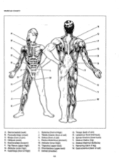
...chest) C. Tibialis Anterior (front of arm) R. Trapezius (upper back) 0. Triceps (back of calf) K. Gluteus Medius (hip) U. Gluteus Maximus (buttocks) V. Adductor (inner thigh) N. Rhomboideus (upper back) P. MUSCLE CHART R S L LI Jll J A. Deltoid (shoulder) in Q. Gastrocnemius (back of arm...) D. Biceps (front of calf) Brachioradials (forearm) F. Hip Flexors (upper thigh) G. Soleus (front of thigh) J. Latissimus Dorsi (mid back) S. Spinae Erectors (lower back) T....
...chest) C. Tibialis Anterior (front of arm) R. Trapezius (upper back) 0. Triceps (back of calf) K. Gluteus Medius (hip) U. Gluteus Maximus (buttocks) V. Adductor (inner thigh) N. Rhomboideus (upper back) P. MUSCLE CHART R S L LI Jll J A. Deltoid (shoulder) in Q. Gastrocnemius (back of arm...) D. Biceps (front of calf) Brachioradials (forearm) F. Hip Flexors (upper thigh) G. Soleus (front of thigh) J. Latissimus Dorsi (mid back) S. Spinae Erectors (lower back) T....

English Manual
Page 17
MONDAY Date: / / EXERCISE WEIGHT SETS REPS TUESDAY Date: / / AEROBIC EXERCISE WEDNESDAY Date: / / EXERCISE WEIGHT SETS REPS THURSDAY Date: / / AEROBIC EXERCISE FRIDAY Date: / / EXERCISE WEIGHT SETS REPS Make photocopies of this page for scheduling and recording your workouts.
MONDAY Date: / / EXERCISE WEIGHT SETS REPS TUESDAY Date: / / AEROBIC EXERCISE WEDNESDAY Date: / / EXERCISE WEIGHT SETS REPS THURSDAY Date: / / AEROBIC EXERCISE FRIDAY Date: / / EXERCISE WEIGHT SETS REPS Make photocopies of this page for scheduling and recording your workouts.

English Manual
Page 18
... 1 1 1 Description "U" Bracket Adjustment Tube Leg Lever Stabilizer Seat Weight Stop Lat Bar Adjustment Weight Rest Pad Tube 1" Round Inner Cap 3/4" Round Inner Cap 1 1/4" Round Inner Cap Main Upright Bench Base Spring Clip Cable Clip 2" Square Inner Cap 1/2" x 1 1/8" Spacer Foam Pad Bench Frame Seat Bracket Cable Weight Carriage 2 1/2" Square Bushing Carriage Stop 1" Anola Cap Right Base User's Manual Exercise Poster Note: "#" indicates a non-illustrated part. Specifications are subject to change without notice. PART LIST Model No. WEBE35560...
... 1 1 1 Description "U" Bracket Adjustment Tube Leg Lever Stabilizer Seat Weight Stop Lat Bar Adjustment Weight Rest Pad Tube 1" Round Inner Cap 3/4" Round Inner Cap 1 1/4" Round Inner Cap Main Upright Bench Base Spring Clip Cable Clip 2" Square Inner Cap 1/2" x 1 1/8" Spacer Foam Pad Bench Frame Seat Bracket Cable Weight Carriage 2 1/2" Square Bushing Carriage Stop 1" Anola Cap Right Base User's Manual Exercise Poster Note: "#" indicates a non-illustrated part. Specifications are subject to change without notice. PART LIST Model No. WEBE35560...

English Manual
Page 20
..., please be prepared to give the following information when calling: 1. The MODEL NUMBER of the product (WEIDER° PRO 355 Weight Bench). 3. Part No. 131133 R1096A Printed in China © 1996 ICON Health & Fitness, Inc. The KEY NUMBER and DESCRIPTION of the desired part(s) (see the front cover of this manual). 4. until 6 p.m. ORDERING REPLACEMENT PARTS To order replacement parts, simply call our Customer Service Department toll-free at 1-800-999-3756, Monday through...
..., please be prepared to give the following information when calling: 1. The MODEL NUMBER of the product (WEIDER° PRO 355 Weight Bench). 3. Part No. 131133 R1096A Printed in China © 1996 ICON Health & Fitness, Inc. The KEY NUMBER and DESCRIPTION of the desired part(s) (see the front cover of this manual). 4. until 6 p.m. ORDERING REPLACEMENT PARTS To order replacement parts, simply call our Customer Service Department toll-free at 1-800-999-3756, Monday through...


