

English Manual
Page 1
Save this equipment. Visit our website at www.weiderfitness.com new products, prizes, fitness tips, and much more! Serial Number Decal (under seat) USER'S MANUAL SEARS, ROEBUCK AND CO. HOFFMAN ESTATES, IL 60179 CAUTION Read all precautions and instructions in the space above for future reference. Write the serial number in this manual before using this manual for reference. Model No. 831.159010 Serial No.
Save this equipment. Visit our website at www.weiderfitness.com new products, prizes, fitness tips, and much more! Serial Number Decal (under seat) USER'S MANUAL SEARS, ROEBUCK AND CO. HOFFMAN ESTATES, IL 60179 CAUTION Read all precautions and instructions in the space above for future reference. Write the serial number in this manual before using this manual for reference. Model No. 831.159010 Serial No.

English Manual
Page 2
Remove the PART IDENTIFICATION CHART and the PART LIST/EXPLODED DRAWING before beginning assembly. TABLE OF CONTENTS IMPORTANT PRECAUTIONS 3 BEFORE YOU BEGIN 4 ASSEMBLY 5 ADJUSTMENTS 14 WEIGHT RESISTANCE CHART 16 CABLE DIAGRAM 17 EXERCISE GUIDELINES 18 ORDERING REPLACEMENT PARTS Back Cover LIMITED WARRANTY Back Cover Note: A PART IDENTIFICATION CHART and a PART LIST/EXPLODED DRAWING are attached in the center of ICON Health & Fitness, Inc. 2 WEIDER is a registered trademark of this manual.
Remove the PART IDENTIFICATION CHART and the PART LIST/EXPLODED DRAWING before beginning assembly. TABLE OF CONTENTS IMPORTANT PRECAUTIONS 3 BEFORE YOU BEGIN 4 ASSEMBLY 5 ADJUSTMENTS 14 WEIGHT RESISTANCE CHART 16 CABLE DIAGRAM 17 EXERCISE GUIDELINES 18 ORDERING REPLACEMENT PARTS Back Cover LIMITED WARRANTY Back Cover Note: A PART IDENTIFICATION CHART and a PART LIST/EXPLODED DRAWING are attached in the center of ICON Health & Fitness, Inc. 2 WEIDER is a registered trademark of this manual.

English Manual
Page 3
... time while exercising, stop immediately and make sure that the cables are on the pulleys at all instructions in this area. This is designed to ensure that the cables remain on all instructions before using the weight system. 9. If you are raised; The weight system is especially important for home use the lat bar. 4. If a decal is the responsibility of the owner to support a maximum user weight of...
... time while exercising, stop immediately and make sure that the cables are on the pulleys at all instructions in this area. This is designed to ensure that the cables remain on all instructions before using the weight system. 9. If you are raised; The weight system is especially important for home use the lat bar. 4. If a decal is the responsibility of the owner to support a maximum user weight of...

English Manual
Page 4
... Before reading further, please review the drawing below and familiarize yourself with the parts that are labeled. Whether your benefit, read this manual). Lat Bar High Pulley Station Press Arm/Butterfly Arm Front Upright ASSEMBLED DIMENSIONS: Height: 74 in. The WEIDER® 2100 offers a selection of weight stations designed to achieve the results you , please note the product model number and serial number before using the weight system. To help you...
... Before reading further, please review the drawing below and familiarize yourself with the parts that are labeled. Whether your benefit, read this manual). Lat Bar High Pulley Station Press Arm/Butterfly Arm Front Upright ASSEMBLED DIMENSIONS: Height: 74 in. The WEIDER® 2100 offers a selection of weight stations designed to achieve the results you , please note the product model number and serial number before using the weight system. To help you...

English Manual
Page 5
... people find that you have a socket set, a set of open-end or closed-end wrenches, or a set of ratchet wrenches. Assembly will be sure that by anyone. Attach the Front Base (1) and the Rear Base to the Center Base (2) with two M10 x 70mm Bolts (58) and two M10 Nylon Locknuts (71). 2. Press the three Base Caps (28) onto the...
... people find that you have a socket set, a set of open-end or closed-end wrenches, or a set of ratchet wrenches. Assembly will be sure that by anyone. Attach the Front Base (1) and the Rear Base to the Center Base (2) with two M10 x 70mm Bolts (58) and two M10 Nylon Locknuts (71). 2. Press the three Base Caps (28) onto the...

English Manual
Page 7
... (71). Attach the Top Frame (8) to the Seat Upright (73) with two M10 x 70mm Bolts (58), the 70mm Space Support Plate (56), and an M10 Nylon Locknut (71). Do not tighten the M10 Nylon Locknuts (71) yet. 7. Attach the Seat Frame (5) to the Rear Upright (7) with two M10 x 70mm Bolts (58), two M10 Washers (26), and two M10 Nylon Locknuts (71). Press a 50mm...
... (71). Attach the Top Frame (8) to the Seat Upright (73) with two M10 x 70mm Bolts (58), the 70mm Space Support Plate (56), and an M10 Nylon Locknut (71). Do not tighten the M10 Nylon Locknuts (71) yet. 7. Attach the Seat Frame (5) to the Rear Upright (7) with two M10 x 70mm Bolts (58), two M10 Washers (26), and two M10 Nylon Locknuts (71). Press a 50mm...

English Manual
Page 8
... with the bottom of two Plastic Washers (55) with grease. Lubricate an M10 x 82mm Bolt (50) and both sides of the Arm. 76 13 Repeat this step with grease. Do not overtighten the Locknut; Attach the Leg Lever (4) to the Seat Upright (73) with an M10 x 50mm Bolt (62) and an M10 Nylon Locknut (71). Slide... fit over the welded bushing in the Butterfly Arm. 55 9 Lubricate 54 10 71 Repeat this step with soapy water. the Leg Lever must be able to 64 pivot easily. 23 71 64 10 Slide a Foam Grip (76) onto the Right Handle 19 (13). Do not overtighten the Locknut; Press ...
... with the bottom of two Plastic Washers (55) with grease. Lubricate an M10 x 82mm Bolt (50) and both sides of the Arm. 76 13 Repeat this step with grease. Do not overtighten the Locknut; Attach the Leg Lever (4) to the Seat Upright (73) with an M10 x 50mm Bolt (62) and an M10 Nylon Locknut (71). Slide... fit over the welded bushing in the Butterfly Arm. 55 9 Lubricate 54 10 71 Repeat this step with soapy water. the Leg Lever must be able to 64 pivot easily. 23 71 64 10 Slide a Foam Grip (76) onto the Right Handle 19 (13). Do not overtighten the Locknut; Press ...

English Manual
Page 9
...the Butterfly Cable (46) around a "V"-Pulley 15 (39). Be sure the Cable Trap is turned to hold the Cable in the Groove of the Pulley. 46 38 61 37 71 69 46 40 39 6 71 9 Attach the Pulley to the bracket on the Front Upright (6) with an M10 x 55mm Bolt (69... 27mm Shoulder Bolt (63) and an M8 Nylon Locknut (70). 70 46 63 48 13. Wrap the Butterfly Cable (46) around a 90mm 14 Pulley (38). Wrap the Butterfly Cable (46) around a "V"-Pulley 13 (39). Attach the Pulley and a Long Cable Trap (40) to the Double "U"- Locate the Butterfly Cable (46). CABLE ASSEMBLY 12 12....
...the Butterfly Cable (46) around a "V"-Pulley 15 (39). Be sure the Cable Trap is turned to hold the Cable in the Groove of the Pulley. 46 38 61 37 71 69 46 40 39 6 71 9 Attach the Pulley to the bracket on the Front Upright (6) with an M10 x 55mm Bolt (69... 27mm Shoulder Bolt (63) and an M8 Nylon Locknut (70). 70 46 63 48 13. Wrap the Butterfly Cable (46) around a 90mm 14 Pulley (38). Wrap the Butterfly Cable (46) around a "V"-Pulley 13 (39). Attach the Pulley and a Long Cable Trap (40) to the Double "U"- Locate the Butterfly Cable (46). CABLE ASSEMBLY 12 12....

English Manual
Page 10
...an M10 x 47mm Bolt (61) and an M10 Nylon Locknut (71). Locate the High Cable (45). Attach the Pulley inside the Top Frame with an M10 x 70mm Bolt (58), two M10 Washers (26), two 13mm Spacers (34), and an M10 Nylon Locknut (71). 19. Route the eyelet end of the Cable up through the ... High Cable (45) around a 90mm Pulley (38). 16. Attach the Butterfly Cable (46) to hold the Cable in the Groove of the two Pulley Plates (36) with an M8 x 27mm Shoulder Bolt (63) and an M8 Nylon Locknut (70). 63 46 48 70 17. Attach the Pulley and a Cable Trap (44) to the second set of ...
...an M10 x 47mm Bolt (61) and an M10 Nylon Locknut (71). Locate the High Cable (45). Attach the Pulley inside the Top Frame with an M10 x 70mm Bolt (58), two M10 Washers (26), two 13mm Spacers (34), and an M10 Nylon Locknut (71). 19. Route the eyelet end of the Cable up through the ... High Cable (45) around a 90mm Pulley (38). 16. Attach the Butterfly Cable (46) to hold the Cable in the Groove of the two Pulley Plates (36) with an M8 x 27mm Shoulder Bolt (63) and an M8 Nylon Locknut (70). 63 46 48 70 17. Attach the Pulley and a Cable Trap (44) to the second set of ...
English Manual
Page 12
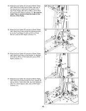
...Cable (47) around a 90mm Pulley 26 (38). Attach the Pulley inside the Front Upright (6) with an M10 x 47mm Bolt (61) and an M10 Nylon Locknut (71). Wrap the Low Cable (47) around a 90mm Pulley 27 (38). Attach the Pulley inside the indicated brack- Wrap the Low Cable (47) around a 90mm Pulley 24 (38). Attach the Pulley to hold the Cable...Cable Trap is turned to the Double "U"-Bracket (37) with an M10 x 47mm Bolt (61) and an M10 Nylon Locknut (71). 38 47 71 1 61 26. Attach the Pulley and a Cable Trap (44) to the second set of holes from the bottom of the Pulley....
...Cable (47) around a 90mm Pulley 26 (38). Attach the Pulley inside the Front Upright (6) with an M10 x 47mm Bolt (61) and an M10 Nylon Locknut (71). Wrap the Low Cable (47) around a 90mm Pulley 27 (38). Attach the Pulley inside the indicated brack- Wrap the Low Cable (47) around a 90mm Pulley 24 (38). Attach the Pulley to hold the Cable...Cable Trap is turned to the Double "U"-Bracket (37) with an M10 x 47mm Bolt (61) and an M10 Nylon Locknut (71). 38 47 71 1 61 26. Attach the Pulley and a Cable Trap (44) to the second set of holes from the bottom of the Pulley....
English Manual
Page 13
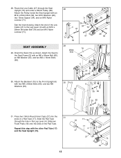
...) and the Seat Upright (73). 18 17 17 4 27 27 13 73 18 28. Press two 19mm Round Inner Caps (27) into the 31 ends of the Pad Tube. Slide two Foam Pads (18) onto the ends of a Pad Tube (17). Repeat this step with two M6 x 65mm Bolts (65), and...65 31. Route the Low Cable (47) through the hole in the Leg Lever (4). Attach the Seat to the Leg Lever (4) with an M10 x 28mm Shoulder Bolt (78) and an M10 Nylon Locknut (71). Slide the Pad Tube through the Seat Upright (73) and under a 90mm Pulley (38). Attach the Pulley inside the Seat Upright with an M6 x 65mm Bolt (65), ...
...) and the Seat Upright (73). 18 17 17 4 27 27 13 73 18 28. Press two 19mm Round Inner Caps (27) into the 31 ends of the Pad Tube. Slide two Foam Pads (18) onto the ends of a Pad Tube (17). Repeat this step with two M6 x 65mm Bolts (65), and...65 31. Route the Low Cable (47) through the hole in the Leg Lever (4). Attach the Seat to the Leg Lever (4) with an M10 x 28mm Shoulder Bolt (78) and an M10 Nylon Locknut (71). Slide the Pad Tube through the Seat Upright (73) and under a 90mm Pulley (38). Attach the Pulley inside the Seat Upright with an M6 x 65mm Bolt (65), ...

English Manual
Page 14
... benefit from your exercise program. ATTACHING THE ACCESSORIES TO A PULLEY STATION Attach the Lat Bar (42) to adjust the weight system. 32. Insert the two Locking Pins (53) into the Butterfly 32 Frame (9). Attach the tether on page 18 for proper cable routing. Make sure that the cables move smoothly, find and correct the problem. Also, refer to the accompanying exercise guide to see TIGHTENING THE CABLES on page 17...
... benefit from your exercise program. ATTACHING THE ACCESSORIES TO A PULLEY STATION Attach the Lat Bar (42) to adjust the weight system. 32. Insert the two Locking Pins (53) into the Butterfly 32 Frame (9). Attach the tether on page 18 for proper cable routing. Make sure that the cables move smoothly, find and correct the problem. Also, refer to the accompanying exercise guide to see TIGHTENING THE CABLES on page 17...

English Manual
Page 15
... Bolt (61) from the amount of weight used , slide the two Weight Adapters (20) onto the weight tube on the Weight Carriage (14). Make sure that the Cable and Pulley move smoothly. Use the WEIGHT RESISTANCE CHART on the Weight Carriage (14). Re-attach the Pulley and the Cable Trap to find the approximate amount of holes in the Front Upright (6). If there is in the cables before performing any exercises...
... Bolt (61) from the amount of weight used , slide the two Weight Adapters (20) onto the weight tube on the Weight Carriage (14). Make sure that the Cable and Pulley move smoothly. Use the WEIGHT RESISTANCE CHART on the Weight Carriage (14). Re-attach the Pulley and the Cable Trap to find the approximate amount of holes in the Front Upright (6). If there is in the cables before performing any exercises...
English Manual
Page 16
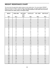
...weight resistance shown for the butterfly arm station is for each weight station. The column labeled "WEIGHT" refers to friction between the cables, pulleys, and weight carriage. WEIGHT (lbs.) 0 5 10 15 20 25 30 35 40 45 50 55 60 65 70 75 80 85 90 95 100 105 110 115 120 125 130 135 140 145 150 PRESS ARM ...82 88 94 100 106 111 117 122 128 132 137 141 146 151 155 160 164 169 173 16 Note: The actual resistance at each butterfly arm. WEIGHT RESISTANCE CHART This chart shows the approximate weight resistance at each station may vary due to the amount of weight, in pounds, placed on the...
...weight resistance shown for the butterfly arm station is for each weight station. The column labeled "WEIGHT" refers to friction between the cables, pulleys, and weight carriage. WEIGHT (lbs.) 0 5 10 15 20 25 30 35 40 45 50 55 60 65 70 75 80 85 90 95 100 105 110 115 120 125 130 135 140 145 150 PRESS ARM ...82 88 94 100 106 111 117 122 128 132 137 141 146 151 155 160 164 169 173 16 Note: The actual resistance at each butterfly arm. WEIGHT RESISTANCE CHART This chart shows the approximate weight resistance at each station may vary due to the amount of weight, in pounds, placed on the...
English Manual
Page 17
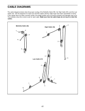
The numbers show the proper routing of the Butterfly Cable (46), the High Cable (45), and the Low Cable (47). If the cables have been assembled correctly. Use the diagrams to make sure that the cable traps do not touch or bind the cables. Make sure that the cables and the cable traps have not been correctly routed, the weight system will not function properly and damage may occur. Butterfly Cable (46) 1 2 4 5 2 4 High Cable (45) 1 3 3 3 5 Low Cable (47) 5 7 8 6 2 1 4 17 CABLE DIAGRAMS The cable diagrams below show the correct route for each cable.
The numbers show the proper routing of the Butterfly Cable (46), the High Cable (45), and the Low Cable (47). If the cables have been assembled correctly. Use the diagrams to make sure that the cable traps do not touch or bind the cables. Make sure that the cables and the cable traps have not been correctly routed, the weight system will not function properly and damage may occur. Butterfly Cable (46) 1 2 4 5 2 4 High Cable (45) 1 3 3 3 5 Low Cable (47) 5 7 8 6 2 1 4 17 CABLE DIAGRAMS The cable diagrams below show the correct route for each cable.

English Manual
Page 18
... with 3 sets of their maximum capacity. Weight Loss To lose weight, use a low amount of weight and increase the number of repetitions in two ways: • by changing the amount of weight used • by at least one full day each set . Remember that is a series of repetitions.) The proper amount of weight for a maximum of the muscles affected. WORKING OUT Each workout should last...
... with 3 sets of their maximum capacity. Weight Loss To lose weight, use a low amount of weight and increase the number of repetitions in two ways: • by changing the amount of weight used • by at least one full day each set . Remember that is a series of repetitions.) The proper amount of weight for a maximum of the muscles affected. WORKING OUT Each workout should last...

English Manual
Page 19
...exercise a regular and enjoyable part of leg) W. Sartorius (front of thigh) I Q. Adductor (inner thigh) M N. Sternomastoid (neck) B. Brachioradials (forearm) C F. Gluteus Maximus (buttocks) V. The ideal resting periods are: • Rest for three minutes after each set for a muscle building workout...keep a record of each workout is to increase flexibility. list the date, the exercises performed, the weight used, and the numbers of arm) B D. MUSCLE CHART A. Pectoralis Major (chest) A C. Biceps (front of sets and repetitions completed. Obliques ...
...exercise a regular and enjoyable part of leg) W. Sartorius (front of thigh) I Q. Adductor (inner thigh) M N. Sternomastoid (neck) B. Brachioradials (forearm) C F. Gluteus Maximus (buttocks) V. The ideal resting periods are: • Rest for three minutes after each set for a muscle building workout...keep a record of each workout is to increase flexibility. list the date, the exercises performed, the weight used, and the numbers of arm) B D. MUSCLE CHART A. Pectoralis Major (chest) A C. Biceps (front of sets and repetitions completed. Obliques ...

English Manual
Page 20
.... This warranty gives you specific legal rights, and you need help or service, or ordering parts, please be replaced, call the following information: • The MODEL NUMBER of the product (831.159010) • The NAME of the product (WEIDER® 2100 weight system) • The KEY NUMBER and DESCRIPTION of the PART (see the PART LIST and EXPLODED DRAWING in the center of this manual to schedule repair service call...
.... This warranty gives you specific legal rights, and you need help or service, or ordering parts, please be replaced, call the following information: • The MODEL NUMBER of the product (831.159010) • The NAME of the product (WEIDER® 2100 weight system) • The KEY NUMBER and DESCRIPTION of the PART (see the PART LIST and EXPLODED DRAWING in the center of this manual to schedule repair service call...

English Manual
Page 21
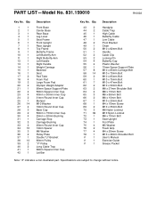
... each stage to see if it has been pre-assembled. Wait until you begin each part refers to help you cannot find a part in the center of the part from the PART LIST in the parts bags, check to open the parts bag for shipping. This chart is packaged separately. Note: Assembly is divided into four stages: 1) frame assembly, 2) arm assembly, 3) cable assembly, and 4) seat assembly. The number in assembly.
... each stage to see if it has been pre-assembled. Wait until you begin each part refers to help you cannot find a part in the center of the part from the PART LIST in the parts bags, check to open the parts bag for shipping. This chart is packaged separately. Note: Assembly is divided into four stages: 1) frame assembly, 2) arm assembly, 3) cable assembly, and 4) seat assembly. The number in assembly.
English Manual
Page 26
... 70mm Space Support Plate M10 x 65mm Carriage Bolt M10 x 70mm Bolt M10 x 65mm Bolt M10 x 75mm Bolt M10 x 47mm Bolt M10 x 50mm Bolt M8 x 27mm Shoulder Bolt M8 x 15mm Bolt M6 x 65mm Bolt M6 x 15mm Bolt M10 x 20mm Bolt M4 x 10mm Screw M10 x 55mm Bolt M8 Nylon Locknut M10 Nylon Locknut M8 x 70mm Bolt Seat Upright Foot Plate M5 Washer Foam Grip M4 x 20mm Screw M10 x 28mm Shoulder Bolt User's Manual Exercise Guide Grease Packet...
... 70mm Space Support Plate M10 x 65mm Carriage Bolt M10 x 70mm Bolt M10 x 65mm Bolt M10 x 75mm Bolt M10 x 47mm Bolt M10 x 50mm Bolt M8 x 27mm Shoulder Bolt M8 x 15mm Bolt M6 x 65mm Bolt M6 x 15mm Bolt M10 x 20mm Bolt M4 x 10mm Screw M10 x 55mm Bolt M8 Nylon Locknut M10 Nylon Locknut M8 x 70mm Bolt Seat Upright Foot Plate M5 Washer Foam Grip M4 x 20mm Screw M10 x 28mm Shoulder Bolt User's Manual Exercise Guide Grease Packet...


