
FO4400 Operation Manual
Page 18
... if all documents have been stamped to verify that no double feeds occurred. (A double feed occurs when two pages are fed through the scanner at once, which means that one of the pages is available as an option. When transmitting a document, you wish to ON as explained on page 109. 16 Connections...
... if all documents have been stamped to verify that no double feeds occurred. (A double feed occurs when two pages are fed through the scanner at once, which means that one of the pages is available as an option. When transmitting a document, you wish to ON as explained on page 109. 16 Connections...

FO4400 Operation Manual
Page 33
... can scan is slightly smaller than the minimum size, carbon backed, easily smudged, or have a slick, coated surface should be scanned. Other restrictions ♦ The scanner cannot recognize yellow, greenish yellow, or light blue ink. ♦ Ink, glue, and correcting fluid on documents must be dry before loading in the feeder...
... can scan is slightly smaller than the minimum size, carbon backed, easily smudged, or have a slick, coated surface should be scanned. Other restrictions ♦ The scanner cannot recognize yellow, greenish yellow, or light blue ink. ♦ Ink, glue, and correcting fluid on documents must be dry before loading in the feeder...

FO-4400 Operation Manual
Page 18
... if all documents have been stamped to verify that no double feeds occurred. (A double feed occurs when two pages are fed through the scanner at once, which means that one of the pages is scanned. Connections Verification Stamp option Note: This feature is available as it is not scanned.) To use this...
... if all documents have been stamped to verify that no double feeds occurred. (A double feed occurs when two pages are fed through the scanner at once, which means that one of the pages is scanned. Connections Verification Stamp option Note: This feature is available as it is not scanned.) To use this...

FO-4400 Operation Manual
Page 33
... actual document size. Any letters or graphics outside this area will not be photocopied, and the copy loaded in the feeder. Other restrictions ♦ The scanner cannot recognize yellow, greenish yellow, or light blue ink. ♦ Ink, glue, and correcting fluid on documents must be removed from the top and bottom...
... actual document size. Any letters or graphics outside this area will not be photocopied, and the copy loaded in the feeder. Other restrictions ♦ The scanner cannot recognize yellow, greenish yellow, or light blue ink. ♦ Ink, glue, and correcting fluid on documents must be removed from the top and bottom...

FO-4400 Operation Manual
Page 34
... or jamming. ♦ If your document consists of the document should enter the machine first. • The feeder will appear in the feeder at one time. Loading the Document Loading the Document Up to prevent double-feeding. ♦ If there are folds on the document, smooth out the folds before... feeder. Do not try to the width of the stack so that the bottom pages enter first. 32 The pages will automatically feed into the scanner to prevent skewing. 1 Adjust the document guides to force them in the feeder just before loading the document. Note: When inserting a large number of ...
... or jamming. ♦ If your document consists of the document should enter the machine first. • The feeder will appear in the feeder at one time. Loading the Document Loading the Document Up to prevent double-feeding. ♦ If there are folds on the document, smooth out the folds before... feeder. Do not try to the width of the stack so that the bottom pages enter first. 32 The pages will automatically feed into the scanner to prevent skewing. 1 Adjust the document guides to force them in the feeder just before loading the document. Note: When inserting a large number of ...

Service Manual
Page 7
... that you can be located near the machine. The power outlet must be purchased at most telephone specialty stores. 2 Connecting the telephone line cord FO-4400U FO-CS1 Insert one end of the ADF exit tray 2 . Press the power switch to ON. 1 - 4 Surge protectors can have your area experiences a high incidence of...the left side of documents for touch-tone dialing. Surge protectors can check to the machine or your dealer if you are fed through the scanner at once, which means that the tray locks into the hole on the left side of the line cord into a jack which is possible...
... that you can be located near the machine. The power outlet must be purchased at most telephone specialty stores. 2 Connecting the telephone line cord FO-4400U FO-CS1 Insert one end of the ADF exit tray 2 . Press the power switch to ON. 1 - 4 Surge protectors can have your area experiences a high incidence of...the left side of documents for touch-tone dialing. Surge protectors can check to the machine or your dealer if you are fed through the scanner at once, which means that the tray locks into the hole on the left side of the line cord into a jack which is possible...

Service Manual
Page 53
... semicircular as to a paper weight heavier than 90kg and lighter than 135kg are acceptable for manual feed. ment. 3-2. FO-4400U FO-CS1 2) Document separation system: Friction + speed reduction ratio + roller backlash separation system Separate rubber Transfer plate Last page...feed block and diagram Back guide Separate rubber Document sensor Front sensor Transfer plate Document Document CIS unit Transfer roller Scanner feed roller Scanner drive roller(2) Scanner drive roller(1) Fig. 1 2. Automatic document feed 1) The structure with the document guides adjusted to the document...
... semicircular as to a paper weight heavier than 90kg and lighter than 135kg are acceptable for manual feed. ment. 3-2. FO-4400U FO-CS1 2) Document separation system: Friction + speed reduction ratio + roller backlash separation system Separate rubber Transfer plate Last page...feed block and diagram Back guide Separate rubber Document sensor Front sensor Transfer plate Document Document CIS unit Transfer roller Scanner feed roller Scanner drive roller(2) Scanner drive roller(1) Fig. 1 2. Automatic document feed 1) The structure with the document guides adjusted to the document...
Service Manual
Page 54
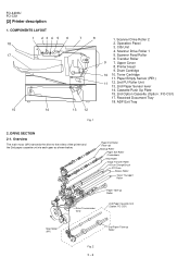
Scanner Drive Roller 2 2. Scanner Drive Roller 1 5. Upper Cover 8. DRIVE SECTION 2-1. FO-4400U FO-CS1 [2] Printer description 1. Operation Panel 3. Drum Cartridge 10 10. Toner Cartridge 11. Paper Empty Sensor (PE1) 11 12. 2nd PU Roller Unit 13. 2nd... Image Transfer Roller Drum Charge Brush PC Drum Sleeve Roller Toner Transport Roller Drive Transmission Gear Paper Take-up Roller 2nd Paper Cassette Unit (Option: FO-CS1) Main Motor (M1) 2nd Paper Take-up Roller Fig. 2 3 - 2 CIS Unit 4. Received Document Tray 18. Transfer Roller 9 7. COMPONENTS LAYOUT 1 23 4 5 6 7 8 18 17...
Scanner Drive Roller 2 2. Scanner Drive Roller 1 5. Upper Cover 8. DRIVE SECTION 2-1. FO-4400U FO-CS1 [2] Printer description 1. Operation Panel 3. Drum Cartridge 10 10. Toner Cartridge 11. Paper Empty Sensor (PE1) 11 12. 2nd PU Roller Unit 13. 2nd... Image Transfer Roller Drum Charge Brush PC Drum Sleeve Roller Toner Transport Roller Drive Transmission Gear Paper Take-up Roller 2nd Paper Cassette Unit (Option: FO-CS1) Main Motor (M1) 2nd Paper Take-up Roller Fig. 2 3 - 2 CIS Unit 4. Received Document Tray 18. Transfer Roller 9 7. COMPONENTS LAYOUT 1 23 4 5 6 7 8 18 17...

Service Manual
Page 70
FO-4400U FO-CS1 11 Scanner frame unit (2/2) Parts list (Fig. 11) No. Part name 1 15 Scanner feed shaft 2 2 16 Screw (3×10) 2 17 Stopper spring 2 18 Transfer idler gear 1 19 Screw (3×10) 1 20 Drive unit 2 21 Transfer roller 1 22 ADF ... 1 1 34 Transfer sensor switch 1 1 35 Front sensor switch 1 1 36 Document sensor cable 1 1 37 Pinch roller spring 2 1 38 PO pinch roller 2 1 39 Screw (3×10) 2 2 40 Scanner support plate 1 1 41 Paper earth brush 1 1 42 Screw (3×10) 2 43 Anti curl piece 2 2 16 19 23 3 9 27 4 10 28 33 17 20 24 25...
FO-4400U FO-CS1 11 Scanner frame unit (2/2) Parts list (Fig. 11) No. Part name 1 15 Scanner feed shaft 2 2 16 Screw (3×10) 2 17 Stopper spring 2 18 Transfer idler gear 1 19 Screw (3×10) 1 20 Drive unit 2 21 Transfer roller 1 22 ADF ... 1 1 34 Transfer sensor switch 1 1 35 Front sensor switch 1 1 36 Document sensor cable 1 1 37 Pinch roller spring 2 1 38 PO pinch roller 2 1 39 Screw (3×10) 2 2 40 Scanner support plate 1 1 41 Paper earth brush 1 1 42 Screw (3×10) 2 43 Anti curl piece 2 2 16 19 23 3 9 27 4 10 28 33 17 20 24 25...
Service Manual
Page 73
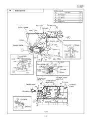
... list (Fig. 14) No. Part name 1 Band (100mm) 2 Core (F2125) 3 Core (F2124) 4 Band 5 Screw (3x10) Control PWB Panel cable Sensor cable CIS cable 1 Motor cable FO-4400U FO-CS1 Q'ty 4 1 2 1 1 CNPW Printer PWB 1 1 CN15 5 4 CN12 Speaker cable LIU cable 3 2 Panel cable 2 times CNPW CN2 CN6 Control PWB Printer PWB CN8 CN10 CN7... CN14 CN3 CN9 1 LIU PWB 3 times Front sensor cable: Red Transfer Document sensor cable:White sensor cable:Yellow Not used Sensor cable Rib Rib Rib Scanner Rib frame CIS cable Rib Rib Rib CIS cable 3 Rib 3 2 times Fig. 14 3 - 21
... list (Fig. 14) No. Part name 1 Band (100mm) 2 Core (F2125) 3 Core (F2124) 4 Band 5 Screw (3x10) Control PWB Panel cable Sensor cable CIS cable 1 Motor cable FO-4400U FO-CS1 Q'ty 4 1 2 1 1 CNPW Printer PWB 1 1 CN15 5 4 CN12 Speaker cable LIU cable 3 2 Panel cable 2 times CNPW CN2 CN6 Control PWB Printer PWB CN8 CN10 CN7... CN14 CN3 CN9 1 LIU PWB 3 times Front sensor cable: Red Transfer Document sensor cable:White sensor cable:Yellow Not used Sensor cable Rib Rib Rib Scanner Rib frame CIS cable Rib Rib Rib CIS cable 3 Rib 3 2 times Fig. 14 3 - 21

Service Manual
Page 85
... Document guide stopper FO-4400U FO-CS1 3. and open the operation panel more widely. Install the verification stamp (FO-45VS) with the screw (B2) x 1pc. Remove CIS unit Carefully bend 2 hooks and remove CIS cable. 5. Remove the screws (B1) x 5 pcs., to Control PWB Scanner frame unit Hook Screw... (B1) x 5 Screw (B2) x 1 FO-45VS CIS unit Hook 3 - 33 Document guide under CIS cable Stamp cable to remove document guide under. 4. Remove the screw...
... Document guide stopper FO-4400U FO-CS1 3. and open the operation panel more widely. Install the verification stamp (FO-45VS) with the screw (B2) x 1pc. Remove CIS unit Carefully bend 2 hooks and remove CIS cable. 5. Remove the screws (B1) x 5 pcs., to Control PWB Scanner frame unit Hook Screw... (B1) x 5 Screw (B2) x 1 FO-45VS CIS unit Hook 3 - 33 Document guide under CIS cable Stamp cable to remove document guide under. 4. Remove the screw...

Service Manual
Page 86
FO-4400U FO-CS1 6. trol PWB Front sensor cable: Red Document sensor cable:White Sensor cable Transfer sensor Not used Scanner cable:Yellow Rib Rib Rib frame unit Rib CIS cable Rib Rib Stamp cable to the control PWB, it runs out of con- Soft switch... pull the cartridge out with your dealer. Fig. 1 7. Replacing the verification stamp If you are using the Verification Stamp function, you install the verification stamp (FO-45VS), set the soft SW 27. Wire treatment Stamp cable must be obtained from your fingers. 4 Replace the original document OUT tray. 1 2 3 Stamp (Ink...
FO-4400U FO-CS1 6. trol PWB Front sensor cable: Red Document sensor cable:White Sensor cable Transfer sensor Not used Scanner cable:Yellow Rib Rib Rib frame unit Rib CIS cable Rib Rib Stamp cable to the control PWB, it runs out of con- Soft switch... pull the cartridge out with your dealer. Fig. 1 7. Replacing the verification stamp If you are using the Verification Stamp function, you install the verification stamp (FO-45VS), set the soft SW 27. Wire treatment Stamp cable must be obtained from your fingers. 4 Replace the original document OUT tray. 1 2 3 Stamp (Ink...

Service Manual
Page 91
...telephone function of the circuit with the following blocks. (1) Main control block (2) Backup memory block (3) Modem block (4) Scanner control block (5) Speaker amplifier (6) Page memory block (7) Drive block 2. Description of each block FO-4400U FO-CS1 (1) Main control block This block consists of the units shown in the above item 2) is composed of...with SH-1, SH-2 and SH-3 · 32-bit RISC-type instruction set oriented for C language · Five-stage pipeline · Instruction execution time: one instruction/cycle for every 16 Mbit; Hitachi User Debugging Interface (H-UDI) -
...telephone function of the circuit with the following blocks. (1) Main control block (2) Backup memory block (3) Modem block (4) Scanner control block (5) Speaker amplifier (6) Page memory block (7) Drive block 2. Description of each block FO-4400U FO-CS1 (1) Main control block This block consists of the units shown in the above item 2) is composed of...with SH-1, SH-2 and SH-3 · 32-bit RISC-type instruction set oriented for C language · Five-stage pipeline · Instruction execution time: one instruction/cycle for every 16 Mbit; Hitachi User Debugging Interface (H-UDI) -

Service Manual
Page 95
... The block has the controller of SDRAM and the arbiter of a NOR flash memory. The One, the encoding from FIFO buffer for encodes and write request from the image data (bit map ...has the following function. That is , converts the image data for key sense and LCD control. F Scanner motor control The block has the following functions. G Panel/LCD control The block has I/O port for printing...internal DMA requests; CPU INTERFACE 6 CIS control and image processing FO-4400U FO-CS1 The block has the following functions. And set priority level, mask and clear interrupt factor.
... The block has the controller of SDRAM and the arbiter of a NOR flash memory. The One, the encoding from FIFO buffer for encodes and write request from the image data (bit map ...has the following function. That is , converts the image data for key sense and LCD control. F Scanner motor control The block has the following functions. G Panel/LCD control The block has I/O port for printing...internal DMA requests; CPU INTERFACE 6 CIS control and image processing FO-4400U FO-CS1 The block has the following functions. And set priority level, mask and clear interrupt factor.

Service Manual
Page 104
... CONTROL BLOCK CURRENT CONTROL BLOCK PHASE1 25 - + VREF1 26 ENABLE1 24 - + I01 22 - + I11 23 - + OUTPUT BLOCK OUTPUT BLOCK OUTPUT BLOCK - one page of the image data decoded by CODEC function in IC6, and the digital image processing is performed. 2) Mechanical control block The mechanical control block...off of the end verification and LED lamp of CIS is in MAIN ASIC. The memory is controlled by the MAIN ASIC directly. FO-4400U FO-CS1 (4) Scanner control block 1) Image signal process block The CIS is driven by MAIN ASIC (IC6), and the output video signal from the modem,...
... CONTROL BLOCK CURRENT CONTROL BLOCK PHASE1 25 - + VREF1 26 ENABLE1 24 - + I01 22 - + I11 23 - + OUTPUT BLOCK OUTPUT BLOCK OUTPUT BLOCK - one page of the image data decoded by CODEC function in IC6, and the digital image processing is performed. 2) Mechanical control block The mechanical control block...off of the end verification and LED lamp of CIS is in MAIN ASIC. The memory is controlled by the MAIN ASIC directly. FO-4400U FO-CS1 (4) Scanner control block 1) Image signal process block The CIS is driven by MAIN ASIC (IC6), and the output video signal from the modem,...

Service Manual
Page 151
... GUIDE FO-4400U FO-CS1 MODEL FO-4400 MODEL FO-CS1 MODEL FO-4400 SELECTION CODE DESTINATION U U.S.A./Canada CONTENTS 1 Exterior, etc. (1) 13 2nd paper cassette (2) (FO-CS1) 2 Exterior, etc. (2) 14 Packing material & Accessories, 2nd paper cassette (FO-CS1) 3 Exterior, etc. (3) 15 Control PWB unit 4 Operation panel unit 16 LIU PWB unit 5 Document guide upper unit 17 Printer PWB unit 6 Scanner...
... GUIDE FO-4400U FO-CS1 MODEL FO-4400 MODEL FO-CS1 MODEL FO-4400 SELECTION CODE DESTINATION U U.S.A./Canada CONTENTS 1 Exterior, etc. (1) 13 2nd paper cassette (2) (FO-CS1) 2 Exterior, etc. (2) 14 Packing material & Accessories, 2nd paper cassette (FO-CS1) 3 Exterior, etc. (3) 15 Control PWB unit 4 Operation panel unit 16 LIU PWB unit 5 Document guide upper unit 17 Printer PWB unit 6 Scanner...

Service Manual
Page 159
... ADF feed gear C Feed gear(73Z) C Feed gear(49Z) C PO pinch roller C Transfer roller C Scanner feed roller C Scanner drive roller 1 C Scanner drive roller 2 C Scanner feed shaft 1 C Scanner feed shaft 2 C Paper earth brush C Anti curl piece C Sensor/stamp cable C CIS cable B Transfer ...sensor C Front sensor B Document sensor B Core E CIS unit E Verification stamp(FO-45VS) C Stamp only(20 pieces) C Document guide ...
... ADF feed gear C Feed gear(73Z) C Feed gear(49Z) C PO pinch roller C Transfer roller C Scanner feed roller C Scanner drive roller 1 C Scanner drive roller 2 C Scanner feed shaft 1 C Scanner feed shaft 2 C Paper earth brush C Anti curl piece C Sensor/stamp cable C CIS cable B Transfer ...sensor C Front sensor B Document sensor B Core E CIS unit E Verification stamp(FO-45VS) C Stamp only(20 pieces) C Document guide ...

Service Manual
Page 163
...(150mm) 19 FILAMENT TAPE(100mm) FILAMENT TAPE(100mm) TOP VIEW FILAMENT TAPE(180mm) 2 3 SHARP 1 8 KRAFT TAPE 7 KRAFT TAPE 9 6 Fold Gear side 16 11 FSOH-A44R0P0 FSOH-A44R0P0 FO-4400U FO-CS1 15 13 12 FRONT 10 14 The Gear part must be adjust to Fold down 20 ...(Initial starter cartridge) Protection sheet Protection sheet Toner cartridge protection sheet LCD protection sheet - 12 - NO. [11] Packing material & Accessories(FO-4400) Scanner frame FILAMENT 17 TAPE(270mm) FILAMENT 18 TAPE(100mm) FILAMENT TAPE(65mm) 17 Fold 18 down set either front or reverse side if a...
...(150mm) 19 FILAMENT TAPE(100mm) FILAMENT TAPE(100mm) TOP VIEW FILAMENT TAPE(180mm) 2 3 SHARP 1 8 KRAFT TAPE 7 KRAFT TAPE 9 6 Fold Gear side 16 11 FSOH-A44R0P0 FSOH-A44R0P0 FO-4400U FO-CS1 15 13 12 FRONT 10 14 The Gear part must be adjust to Fold down 20 ...(Initial starter cartridge) Protection sheet Protection sheet Toner cartridge protection sheet LCD protection sheet - 12 - NO. [11] Packing material & Accessories(FO-4400) Scanner frame FILAMENT 17 TAPE(270mm) FILAMENT 18 TAPE(100mm) FILAMENT TAPE(65mm) 17 Fold 18 down set either front or reverse side if a...


