User's Guide
Page 62
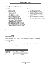
Fuser and ITU Refer to the part number listed on the fuser or ITU for the appropriate reordering number for these items. Ordering a fuser Note: When the 87 Fuser Life Warning message appears on the display, you should order a new toner waste container. .... To order a new toner waste container, order part number 10B3100. Only order a web oiler fuser if an authorized servicer has installed a web oiler upgrade kit to allow your printer. Maintaining the printer The following is a list of cartridges you can order: C780 / C782 • Black print cartridge • Cyan print cartridge...
Fuser and ITU Refer to the part number listed on the fuser or ITU for the appropriate reordering number for these items. Ordering a fuser Note: When the 87 Fuser Life Warning message appears on the display, you should order a new toner waste container. .... To order a new toner waste container, order part number 10B3100. Only order a web oiler fuser if an authorized servicer has installed a web oiler upgrade kit to allow your printer. Maintaining the printer The following is a list of cartridges you can order: C780 / C782 • Black print cartridge • Cyan print cartridge...
User's Guide
Page 63
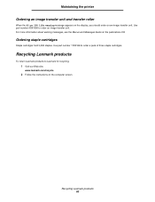
... transfer roller When the 83.yy ITU life warning message appears on the publications CD Ordering staple cartridges Staple cartridges hold 3,000 staples. Recycling Lexmark products To return Lexmark products to order an image transfer unit. Use part number 40X1680 to Lexmark for recycling: 1 Visit our Web site: www.lexmark.com/recycle 2 Follow the instructions on...
... transfer roller When the 83.yy ITU life warning message appears on the publications CD Ordering staple cartridges Staple cartridges hold 3,000 staples. Recycling Lexmark products To return Lexmark products to order an image transfer unit. Use part number 40X1680 to Lexmark for recycling: 1 Visit our Web site: www.lexmark.com/recycle 2 Follow the instructions on...
Help Menu Pages
Page 12
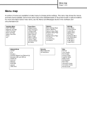
...items available. Some menu items may not be available based on the Software and Documentation CD. Menu map Page 1 of 2 Menu map A number of menus are available to make it easy to change printer settings. For more information about menu items, see the Menus and Messages Guide ...on the printer model or options installed. Supplies Menu Cyan Cartridge Magenta Cartridge Yellow Cartridge Black Cartridge Waste Toner Box Fuser ITU Paper Menu Default Source Paper Size/Type Configure MP Substitute Size Paper Texture Paper Weight Paper Loading Custom Types Universal Setup Bin Setup ...
...items available. Some menu items may not be available based on the Software and Documentation CD. Menu map Page 1 of 2 Menu map A number of menus are available to make it easy to change printer settings. For more information about menu items, see the Menus and Messages Guide ...on the printer model or options installed. Supplies Menu Cyan Cartridge Magenta Cartridge Yellow Cartridge Black Cartridge Waste Toner Box Fuser ITU Paper Menu Default Source Paper Size/Type Configure MP Substitute Size Paper Texture Paper Weight Paper Loading Custom Types Universal Setup Bin Setup ...
Help Menu Pages
Page 20
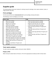
Supplies guide Page 1 of cartridges you can order. Fuser or ITU Refer to the part number listed on the fuser or ITU for the appropriate reordering number for print cartridge ordering information. C780 / C782 C782 • Black print cartridge • Cyan print cartridge • Magenta print cartridge •... yield Return Program print cartridge Toner waste container To order a new toner waste container, order part number 10B3100. Print cartridges Visit the lexmark Web site at www.lexmark.com for these items. The following is a list of 1 Supplies guide The following tables list ...
Supplies guide Page 1 of cartridges you can order. Fuser or ITU Refer to the part number listed on the fuser or ITU for the appropriate reordering number for print cartridge ordering information. C780 / C782 C782 • Black print cartridge • Cyan print cartridge • Magenta print cartridge •... yield Return Program print cartridge Toner waste container To order a new toner waste container, order part number 10B3100. Print cartridges Visit the lexmark Web site at www.lexmark.com for these items. The following is a list of 1 Supplies guide The following tables list ...
Service Manual
Page 121
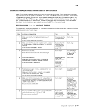
...open cover cable is mounted in the front access door support, and the other switch in the ITU light shield. POR incomplete, Close Door constantly displays This symptom is usually associated with the switch...and a cable. See "System board removal" on page 4-11. Diagnostic information 2-79 Go to step 2 Replace the ITU assembly. See "Front cover or front cover backplate assembly removal" on page 4-89. 5061 Close door/HVPS/printhead interlock ...is correctly installed. These cable/switches provide separate interlocks for the part number.) Replace the ITU light shield assembly.
...open cover cable is mounted in the front access door support, and the other switch in the ITU light shield. POR incomplete, Close Door constantly displays This symptom is usually associated with the switch...and a cable. See "System board removal" on page 4-11. Diagnostic information 2-79 Go to step 2 Replace the ITU assembly. See "Front cover or front cover backplate assembly removal" on page 4-89. 5061 Close door/HVPS/printhead interlock ...is correctly installed. These cable/switches provide separate interlocks for the part number.) Replace the ITU light shield assembly.
Service Manual
Page 122
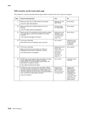
... cable assembly" on page 7-37 for continuity between J14-1 and J14-2 on the system board and the ITU autoconnect is not broken. Is the ITU light shield out of position. Check for part number.) 2-80 Service Manual Go to step 4 Install the front cover correctly, or repair as necessary. No ...Go to step 2 Go to step 3 Go to step 5 Replace the front cover. Is there continuity? Replace the ITU assembly. Step Actions and questions 1 Make...
... cable assembly" on page 7-37 for continuity between J14-1 and J14-2 on the system board and the ITU autoconnect is not broken. Is the ITU light shield out of position. Check for part number.) 2-80 Service Manual Go to step 4 Install the front cover correctly, or repair as necessary. No ...Go to step 2 Go to step 3 Go to step 5 Replace the front cover. Is there continuity? Replace the ITU assembly. Step Actions and questions 1 Make...
Service Manual
Page 170
...: • All downloaded resources (fonts, macros, symbol sets) in the printer memory are being restored, and y represents the total number of paper from The printer automatically senses media removal and resumes printing. Restoring Factory Defaults Wait for the message to print. All settings ... of life. • Replace the image transfer unit. Wait for the message to clear. • Select Quit restoring to clear. Replace ITU • Image transfer unit is cleared, the printer will post the warning again. The Display Language setting in the Parallel Menu, Serial Menu...
...: • All downloaded resources (fonts, macros, symbol sets) in the printer memory are being restored, and y represents the total number of paper from The printer automatically senses media removal and resumes printing. Restoring Factory Defaults Wait for the message to print. All settings ... of life. • Replace the image transfer unit. Wait for the message to clear. • Select Quit restoring to clear. Replace ITU • Image transfer unit is cleared, the printer will post the warning again. The Display Language setting in the Parallel Menu, Serial Menu...
Service Manual
Page 212
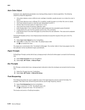
... a new or different color cartridge is installed, usually at power on or when the cover is closed. • If the printer detects a new or different ITU is installed, usually at power on or when the cover is closed. • If the fuser detects at power on that the fuser temperature is... Sharpening from 100 to how many pages since the last calibration. Use to increase the value. Select Auto Color Adjust from the Config Menu. 2. The number refers to 1000. For example, if the value is at 60° C. • If Power Saver has been active for font data. Select Paper Prompts...
... a new or different color cartridge is installed, usually at power on or when the cover is closed. • If the printer detects a new or different ITU is installed, usually at power on or when the cover is closed. • If the fuser detects at power on that the fuser temperature is... Sharpening from 100 to how many pages since the last calibration. Use to increase the value. Select Auto Color Adjust from the Config Menu. 2. The number refers to 1000. For example, if the value is at 60° C. • If Power Saver has been active for font data. Select Paper Prompts...
Service Manual
Page 230
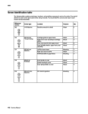
.... 5061 Screw identification table The following table contains screw types, locations, and quantities necessary to gearbox Machine Mounting 4 4-2 Service Manual Reference number 002 Screw type 4-40 Machine Location Parallel connector to shield Purpose Qty Attach 2 102 M3.5x8 mm Cartridge guides to upper frame Attach ... handle to cover Panhead Detent housing to cover Door spring shields to cover Attach 2 Attach 1 Attach 4 214 M3.5x10 mm ITU motor to service the printer. You must install the correct screw type in each screw type location when doing removals.
.... 5061 Screw identification table The following table contains screw types, locations, and quantities necessary to gearbox Machine Mounting 4 4-2 Service Manual Reference number 002 Screw type 4-40 Machine Location Parallel connector to shield Purpose Qty Attach 2 102 M3.5x8 mm Cartridge guides to upper frame Attach ... handle to cover Panhead Detent housing to cover Door spring shields to cover Attach 2 Attach 1 Attach 4 214 M3.5x10 mm ITU motor to service the printer. You must install the correct screw type in each screw type location when doing removals.
Service Manual
Page 231
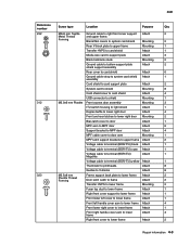
5061 Reference number Screw type Location Purpose Qty 232 M3x6 mm Taptite Ground cable to lower frame Attach 2 Repair information 4-3 Forming Blank INA covers to system card shield ... to shield Mounting 8 Card shield cover to card shield Attach 4 USB connector to shield Mounting 1 312 M2.9x6 mm Plastite Front access door assembly Mounting 3 ITU switch housing to light shield Attach 1 Duplex baffle to lower right door Attach 4 Front and rear latches to lower right door Mounting 2 Bias latch cover...
5061 Reference number Screw type Location Purpose Qty 232 M3x6 mm Taptite Ground cable to lower frame Attach 2 Repair information 4-3 Forming Blank INA covers to system card shield ... to shield Mounting 8 Card shield cover to card shield Attach 4 USB connector to shield Mounting 1 312 M2.9x6 mm Plastite Front access door assembly Mounting 3 ITU switch housing to light shield Attach 1 Duplex baffle to lower right door Attach 4 Front and rear latches to lower right door Mounting 2 Bias latch cover...
Service Manual
Page 232
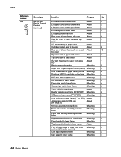
5061 Reference number Screw type Location Purpose Qty 323 M3.5x8 mm Left lower cover ...Top cover asm to upper front cover Attach 3 Top cover asm to card shield Attach 1 ITU light shield asm to upper front guide Attach 1 ITU Ribs to upper redrive door Mounting 5 Upper door hinges to upper frame (redrive) Mounting 2...to upper frame (redrive) Mounting 2 Developer HVPS to cartridge contact asm Mounting 4 BOR drive asm to upper frame Mounting 1 ITU drive asm to lower frame Mounting 3 Fuser drive asm to lower frame Mounting 4 Vacuum top duct to lower frame Mounting 2...
5061 Reference number Screw type Location Purpose Qty 323 M3.5x8 mm Left lower cover ...Top cover asm to upper front cover Attach 3 Top cover asm to card shield Attach 1 ITU light shield asm to upper front guide Attach 1 ITU Ribs to upper redrive door Mounting 5 Upper door hinges to upper frame (redrive) Mounting 2...to upper frame (redrive) Mounting 2 Developer HVPS to cartridge contact asm Mounting 4 BOR drive asm to upper frame Mounting 1 ITU drive asm to lower frame Mounting 3 Fuser drive asm to lower frame Mounting 4 Vacuum top duct to lower frame Mounting 2...
Service Manual
Page 263
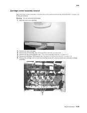
Open the front cover assembly. 2. Remove the ITU assembly. See "ITU assembly removal" on page 4-39. 6. Remove the developer HVPS board. Warning: Do not remove the printheads. 1. Remove the cartridge rail front and rear mounting screws ... assembly. See "Developer HVPS board removal" on page 4-49. 4. Remove the toner cartridges. 3. See "Top cover assembly removal" on page 7-28 for the part numbers. A Repair information 4-35 5061 Cartridge contact assembly removal See "Cartridge contact assembly, complete Also order cable tie parts packet (P/N 40X1648)" on page 4-13. 5.
Open the front cover assembly. 2. Remove the ITU assembly. See "ITU assembly removal" on page 4-39. 6. Remove the developer HVPS board. Warning: Do not remove the printheads. 1. Remove the cartridge rail front and rear mounting screws ... assembly. See "Developer HVPS board removal" on page 4-49. 4. Remove the toner cartridges. 3. See "Top cover assembly removal" on page 7-28 for the part numbers. A Repair information 4-35 5061 Cartridge contact assembly removal See "Cartridge contact assembly, complete Also order cable tie parts packet (P/N 40X1648)" on page 4-13. 5.
Service Manual
Page 277
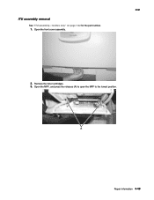
Repair information 4-49 Open the MPF, and press the releases (A) to open the MPF to the lowest position. Remove the toner cartridges. 3. ITU assembly removal See "ITU assembly-1xx/3xx only" on page 7-22 for the part number. 1. Open the front cover assembly. 5061 2.
Repair information 4-49 Open the MPF, and press the releases (A) to open the MPF to the lowest position. Remove the toner cartridges. 3. ITU assembly removal See "ITU assembly-1xx/3xx only" on page 7-22 for the part number. 1. Open the front cover assembly. 5061 2.
Service Manual
Page 280
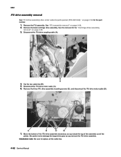
... large drive gear as you remove the ITU drive assembly. A 4. See the removal for the part number. 1. 5061 ITU drive assembly removal See "ITU drive assembly Also order cable tie parts packet (P/N 40X1648)." See "ITU assembly removal" on page 4-38. 3. Remove the ITU assembly. Move the bottom of the ITU drive assembly toward you as you rotate...
... large drive gear as you remove the ITU drive assembly. A 4. See the removal for the part number. 1. 5061 ITU drive assembly removal See "ITU drive assembly Also order cable tie parts packet (P/N 40X1648)." See "ITU assembly removal" on page 4-38. 3. Remove the ITU assembly. Move the bottom of the ITU drive assembly toward you as you rotate...
Service Manual
Page 307
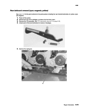
Remove the ITU assembly. See "ITU assembly removal" on page 4-49. 4. Repair information 4-79 5061 Rear bellcrank removal (cyan, magenta, yellow) See page 7-25 for the part numbers for the parts packet, including the rear transfer bellcranks, for cracks or breakage. 5. Remove the spring (A). Power off the printer. 2. Check each of the rear bellcranks for yellow, cyan, and magenta. 1. Remove the four toner cartridges, and leave the front door open. 3.
Remove the ITU assembly. See "ITU assembly removal" on page 4-49. 4. Repair information 4-79 5061 Rear bellcrank removal (cyan, magenta, yellow) See page 7-25 for the part numbers for the parts packet, including the rear transfer bellcranks, for cracks or breakage. 5. Remove the spring (A). Power off the printer. 2. Check each of the rear bellcranks for yellow, cyan, and magenta. 1. Remove the four toner cartridges, and leave the front door open. 3.
Service Manual
Page 309
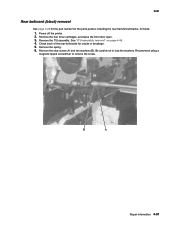
Remove the stop screw (A) and two washers (B). See "ITU assembly removal" on page 4-49. 4. Remove the spring. 6. Repair information 4-81 Power off the printer. 2. Be careful not to remove the screw. 5061 Rear bellcrank (black) removal See page 7-25 for the part number for the parts packet, including the rear transfer bellcranks, for cracks or breakage. 5. Check each of the rear bellcranks for black. 1. Remove the four toner cartridges, and leave the front door open. 3. Recommend using a magnetic tipped screwdriver to lose the washers. Remove the ITU assembly.
Remove the stop screw (A) and two washers (B). See "ITU assembly removal" on page 4-49. 4. Remove the spring. 6. Repair information 4-81 Power off the printer. 2. Be careful not to remove the screw. 5061 Rear bellcrank (black) removal See page 7-25 for the part number for the parts packet, including the rear transfer bellcranks, for cracks or breakage. 5. Check each of the rear bellcranks for black. 1. Remove the four toner cartridges, and leave the front door open. 3. Recommend using a magnetic tipped screwdriver to lose the washers. Remove the ITU assembly.
Service Manual
Page 316
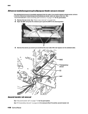
... See "Second transfer roll" on page 4-22. 2. See "Rear cover removal" on page 7-12 for the part number. See "ITU assembly removal" on page 7-37 for removal of the ITU and the second transfer roll. 4-88 Service Manual See "S2/XPAR/NMS/MPF cable assembly (with sensors)" on page ...4-49 for the part number. 1. Remove the rear cover. 5061 S2/narrow media/transparency/multipurpose feeder sensors removal The individual...
... See "Second transfer roll" on page 4-22. 2. See "Rear cover removal" on page 7-12 for the part number. See "ITU assembly removal" on page 7-37 for removal of the ITU and the second transfer roll. 4-88 Service Manual See "S2/XPAR/NMS/MPF cable assembly (with sensors)" on page ...4-49 for the part number. 1. Remove the rear cover. 5061 S2/narrow media/transparency/multipurpose feeder sensors removal The individual...
Service Manual
Page 322
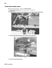
Remove tray 1. 3. Lifting and rotate the right edge of the transfer plate. 5061 Transfer plate assembly removal See "Transfer plate assembly" on page 4-49. 2. Remove the ITU assembly. See "ITU assembly removal" on page 7-12 for the part number. 1. Remove the grounding strap (A) attached to the bottom of the transfer plate up to a 45° angle to release the transfer plate. 4. Remove the transfer plate assembly. 4-94 Service Manual A 5.
Remove tray 1. 3. Lifting and rotate the right edge of the transfer plate. 5061 Transfer plate assembly removal See "Transfer plate assembly" on page 4-49. 2. Remove the ITU assembly. See "ITU assembly removal" on page 7-12 for the part number. 1. Remove the grounding strap (A) attached to the bottom of the transfer plate up to a 45° angle to release the transfer plate. 4. Remove the transfer plate assembly. 4-94 Service Manual A 5.
Service Manual
Page 363
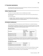
...Lexmark attachments Scheduled maintenance The operator panel displays 80 Fuser Maintenance and 83 ITU Maintenance for scheduled maintenance. 80 Fuser Maintenance is displayed at 120,000 copies for C78x models, and at each 100,000 copies when the Web Oiler Assembly is displayed at the same time. Check the following part numbers... fuser Maintenance kit 100 V fuser Part number Models 1xx/3xx (C77x) 40X1859 40X1860 40X1861 Models 2xx/4xx (C78x) 40X1831 40X1832 40X1833 83 ITU Maintenance is displayed at 200,000 copies for part number. Follow these recommendations to "Web Oiler ...
...Lexmark attachments Scheduled maintenance The operator panel displays 80 Fuser Maintenance and 83 ITU Maintenance for scheduled maintenance. 80 Fuser Maintenance is displayed at 120,000 copies for C78x models, and at each 100,000 copies when the Web Oiler Assembly is displayed at the same time. Check the following part numbers... fuser Maintenance kit 100 V fuser Part number Models 1xx/3xx (C77x) 40X1859 40X1860 40X1861 Models 2xx/4xx (C78x) 40X1831 40X1832 40X1833 83 ITU Maintenance is displayed at 200,000 copies for part number. Follow these recommendations to "Web Oiler ...
Service Manual
Page 388
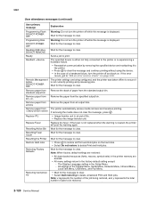
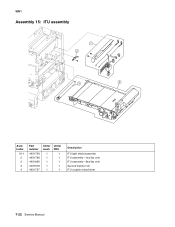
5061 Assembly 15: ITU assembly 1 4 3 2 AsmIndex 15-1 2 2 3 4 Part number 40X1739 40X1788 40X1826 40X1678 40X1737 Units/ mach 1 1 1 1 1 Units/ FRU 1 1 1 1 1 Description ITU light shield assembly ITU assembly-1xx/3xx only ITU assembly-2xx/4xx only Second transfer roll ITU coupler retract lever 7-22 Service Manual
5061 Assembly 15: ITU assembly 1 4 3 2 AsmIndex 15-1 2 2 3 4 Part number 40X1739 40X1788 40X1826 40X1678 40X1737 Units/ mach 1 1 1 1 1 Units/ FRU 1 1 1 1 1 Description ITU light shield assembly ITU assembly-1xx/3xx only ITU assembly-2xx/4xx only Second transfer roll ITU coupler retract lever 7-22 Service Manual


