Service Manual
Page 9
5061 Low voltage power supply (LVPS 5-23 LVPS cable connectors to system board 5-23 LVPS fuser connectors 5-24 Media size sensing board 5-25 High-capacity input tray (HCIT 5-26 StapleSmart ...
5061 Low voltage power supply (LVPS 5-23 LVPS cable connectors to system board 5-23 LVPS fuser connectors 5-24 Media size sensing board 5-25 High-capacity input tray (HCIT 5-26 StapleSmart ...
Service Manual
Page 41
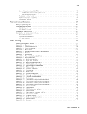
...-Only Memory Electrostatic Discharge Field Replaceable Unit Gigabyte High-Capacity Input Tray High-Capacity Output Finisher High Voltage Power Supply Image Transfer Unit Black Light Amplification by Stimulated Emission of Radiation Liquid Crystal Display Light-Emitting Diode Low Voltage Power Supply Magenta Masked Read Only Memory Microswitch Nonvolatile Random Access Memory Original Equipment Manufacturer Optical Sensor Photoconductor...
...-Only Memory Electrostatic Discharge Field Replaceable Unit Gigabyte High-Capacity Input Tray High-Capacity Output Finisher High Voltage Power Supply Image Transfer Unit Black Light Amplification by Stimulated Emission of Radiation Liquid Crystal Display Light-Emitting Diode Low Voltage Power Supply Magenta Masked Read Only Memory Microswitch Nonvolatile Random Access Memory Original Equipment Manufacturer Optical Sensor Photoconductor...
Service Manual
Page 116
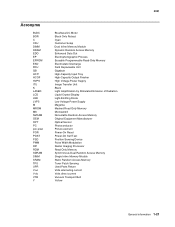
Is the AC line voltage correct? 5 Low voltage power supply-Turn the power off , the LCD display is located. Replace the line cord. 5061 AC and DC power service check Before proceeding with this service check, turn . No Inform the customer that AC power to the proper power setting for the geographic ...are in poor condition, replace the cord. Is the AC line voltage correct? 3 AC power cord Is the power cord in good condition and correctly installed? 4 AC power check (AC line cord)-Check the AC line voltage at a time until the failing option is blank, the fuser ...
Is the AC line voltage correct? 5 Low voltage power supply-Turn the power off , the LCD display is located. Replace the line cord. 5061 AC and DC power service check Before proceeding with this service check, turn . No Inform the customer that AC power to the proper power setting for the geographic ...are in poor condition, replace the cord. Is the AC line voltage correct? 3 AC power cord Is the power cord in good condition and correctly installed? 4 AC power check (AC line cord)-Check the AC line voltage at a time until the failing option is blank, the fuser ...
Service Manual
Page 344
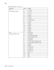
Connector J18 Low voltage power supply J19 Magenta/cyan BLDC motors Pin no. 1 2 3 4 5 6 7 8 9 10 11 12 13 14 15 16 1 2 3 4 5 6 7 8 9 10 11 12 13 14 15 16 17 18 Signal +3.3 V dc +3.3 V dc +5 V dc +5 V dc +24V dc +24V dc +24V dc +3.3 V dc Sense Ground Ground Ground Ground Ground Ground Ground Ground M_ON_OUT C_ON_OUT +5V dc (Through fuse F8) +5V dc (Through fuse F8) M_DIR_OUT C_DIR_OUT +24V_M_AND_C (Through fuse F5) +24V_M_AND_C (Through fuse F5) Ground Ground M_CLK_OUT C_CLK_OUT M_HALL_IN C_HALL_IN N/C N/C N/C N/C 5-12 Service Manual 5061 See "System board" on page 5-7.
Connector J18 Low voltage power supply J19 Magenta/cyan BLDC motors Pin no. 1 2 3 4 5 6 7 8 9 10 11 12 13 14 15 16 1 2 3 4 5 6 7 8 9 10 11 12 13 14 15 16 17 18 Signal +3.3 V dc +3.3 V dc +5 V dc +5 V dc +24V dc +24V dc +24V dc +3.3 V dc Sense Ground Ground Ground Ground Ground Ground Ground Ground M_ON_OUT C_ON_OUT +5V dc (Through fuse F8) +5V dc (Through fuse F8) M_DIR_OUT C_DIR_OUT +24V_M_AND_C (Through fuse F5) +24V_M_AND_C (Through fuse F5) Ground Ground M_CLK_OUT C_CLK_OUT M_HALL_IN C_HALL_IN N/C N/C N/C N/C 5-12 Service Manual 5061 See "System board" on page 5-7.
Service Manual
Page 346
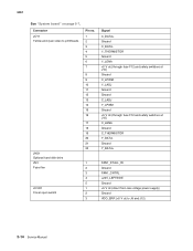
... C_LADJ Y_LPWM Ground +5 V dc (through fuse F12 and safety switches at J10) C_LENA Ground C_THERMISTOR Y_DATAGround Y_DATA+ FAN1_STALL_IN Ground FAN1_CNTRL +24V_LEFTSIDE Ground +5 V dc (direct from low voltage power supply) Ground VDO_ERR (+5 V dc to J8 and J12) 5-14 Service Manual
... C_LADJ Y_LPWM Ground +5 V dc (through fuse F12 and safety switches at J10) C_LENA Ground C_THERMISTOR Y_DATAGround Y_DATA+ FAN1_STALL_IN Ground FAN1_CNTRL +24V_LEFTSIDE Ground +5 V dc (direct from low voltage power supply) Ground VDO_ERR (+5 V dc to J8 and J12) 5-14 Service Manual
Service Manual
Page 355
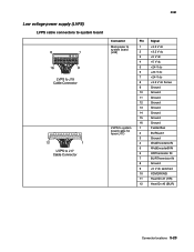
5061 Low voltage power supply (LVPS) LVPS cable connectors to system board Connector Main power to system board (J35) LVPS to system board cable for fuser (J17) Pin Signal 1 +3.3 V dc 2 +3.3 V dc 3 +5 V dc 4 +5 V dc 5 +24 V dc 6 +24 V dc 7 +24 V dc 8 +3.3 V dc ...
5061 Low voltage power supply (LVPS) LVPS cable connectors to system board Connector Main power to system board (J35) LVPS to system board cable for fuser (J17) Pin Signal 1 +3.3 V dc 2 +3.3 V dc 3 +5 V dc 4 +5 V dc 5 +24 V dc 6 +24 V dc 7 +24 V dc 8 +3.3 V dc ...
Service Manual
Page 455
... 2-14, 2-17 ITU drive assembly location 5-2 lubrication 6-3 parts catalog 7-23 removal 4-52 J Jobs On Disk 3-35 L LCD Brightness 2-123 LCD Contrast 2-123 LCD Test 3-15 low voltage power supply (LVPS) connections 5-23, 5-24 location 5-1 parts catalog 7-31 removal 4-53 service check 2-55 lubrication cartridge drive assembly replacement 6-3 fuser drive assembly replacement 6-2 ITU drive assembly...
... 2-14, 2-17 ITU drive assembly location 5-2 lubrication 6-3 parts catalog 7-23 removal 4-52 J Jobs On Disk 3-35 L LCD Brightness 2-123 LCD Contrast 2-123 LCD Test 3-15 low voltage power supply (LVPS) connections 5-23, 5-24 location 5-1 parts catalog 7-31 removal 4-53 service check 2-55 lubrication cartridge drive assembly replacement 6-3 fuser drive assembly replacement 6-2 ITU drive assembly...


