Owner's Manual (English)
Page 3
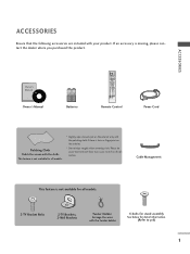
...all models. * Slightly wipe stained spot on the exterior only with the polishing cloth if there is not available for all models. 2-TV Bracket Bolts 2-TV Brackets, 2-Wall Brackets Twister Holder Arrange the wires with the twister holder. 4-bolts for stand assembly See below for detail information. (... missing, please contact the dealer where you purchased the product. Owner's Manual 1.5V 1.5V Batteries INPUT D/A INPUT POWER SIMPLINK BRIGHT MODE TV VCR DVD RATIO TEXT INFO i GUIDE i SUBTITLE MENU LIST EXIT FAV OK VOL Q.VIEW PR PAGE MUTE 1 2 3 4 5 6 7 8 9 APM ...
...all models. * Slightly wipe stained spot on the exterior only with the polishing cloth if there is not available for all models. 2-TV Bracket Bolts 2-TV Brackets, 2-Wall Brackets Twister Holder Arrange the wires with the twister holder. 4-bolts for stand assembly See below for detail information. (... missing, please contact the dealer where you purchased the product. Owner's Manual 1.5V 1.5V Batteries INPUT D/A INPUT POWER SIMPLINK BRIGHT MODE TV VCR DVD RATIO TEXT INFO i GUIDE i SUBTITLE MENU LIST EXIT FAV OK VOL Q.VIEW PR PAGE MUTE 1 2 3 4 5 6 7 8 9 APM ...
Owner's Manual (English)
Page 4
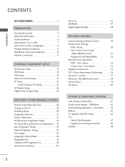
...18 ...Other A/V Source Setup 21 PC Setup 22 ...- Picture Improvement Technology 56 Advanced - Cinema 57 Advanced - User Mode 63 Balance 65 TV Speakers ON/OFF Setup 66 I/II - Speaker Sound Output Selection 67 Subtitle 68 2 Black(Darkness) Level 58 Picture Preset 59 ...XD ...Back Panel Information 5 Stand Installation 6 Attaching the TV to a Wall 7 Back Cover for PC Mode 25 AV Output Setup 26 ...Digital Audio Output Setup 27 WATCHING TV/PROGRAMME CONTROL Remote Control Key Functions 28 Turning on the TV 30 Initializing Setup 30 Programme Selection 31 Volume ...
...18 ...Other A/V Source Setup 21 PC Setup 22 ...- Picture Improvement Technology 56 Advanced - Cinema 57 Advanced - User Mode 63 Balance 65 TV Speakers ON/OFF Setup 66 I/II - Speaker Sound Output Selection 67 Subtitle 68 2 Black(Darkness) Level 58 Picture Preset 59 ...XD ...Back Panel Information 5 Stand Installation 6 Attaching the TV to a Wall 7 Back Cover for PC Mode 25 AV Output Setup 26 ...Digital Audio Output Setup 27 WATCHING TV/PROGRAMME CONTROL Remote Control Key Functions 28 Turning on the TV 30 Initializing Setup 30 Programme Selection 31 Volume ...
Owner's Manual (English)
Page 6
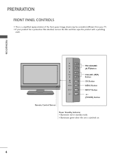
PREPARATION PR VOL OK MENU R INPUT PROGRAMME (D,E)Button VOLUME (F,G) Button OK Button MENU Button INPUT Button (POWER) Button Remote Control Sensor Power Standby Indicator • Illuminates red in standby mode. • Illuminates green when the set is a simplified representation of the front panel. PREPARATION FRONT PANEL CONTROLS I If your TV. I This is switched on. 4 Image shown may be somewhat different from your product has a protection film attached, remove the film and then wipe the product with a polishing cloth.
PREPARATION PR VOL OK MENU R INPUT PROGRAMME (D,E)Button VOLUME (F,G) Button OK Button MENU Button INPUT Button (POWER) Button Remote Control Sensor Power Standby Indicator • Illuminates red in standby mode. • Illuminates green when the set is a simplified representation of the front panel. PREPARATION FRONT PANEL CONTROLS I If your TV. I This is switched on. 4 Image shown may be somewhat different from your product has a protection film attached, remove the film and then wipe the product with a polishing cloth.
Owner's Manual (English)
Page 7
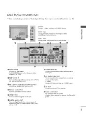
S-VIDEO Connect S-Video out from an S-VIDEO device. 9 AV OUT Connect a second TV or monitor. 10 Power Cord Socket For operation with a HDMI to DVI cable. 2 ANTENNA IN RGB/AUDIO IN DIGITAL Connect the output from a set top ... S-VIDEO VIDEO (MONO) AUDIO 89 1 HDMI/DVI IN Connect a HDMI signal. AUDIO Input Connections are available for listening to operate the TV on a PC. 4 Remote Control Port Connect your TV. RGB IN RGB (PC) AUDIO (RGB/DVI) ANTENNA IN REMOTE CONTROL IN DIGITAL AUDIO OUT OPTICAL VIDEO OUT COMPONENT IN RS-232C...
S-VIDEO Connect S-Video out from an S-VIDEO device. 9 AV OUT Connect a second TV or monitor. 10 Power Cord Socket For operation with a HDMI to DVI cable. 2 ANTENNA IN RGB/AUDIO IN DIGITAL Connect the output from a set top ... S-VIDEO VIDEO (MONO) AUDIO 89 1 HDMI/DVI IN Connect a HDMI signal. AUDIO Input Connections are available for listening to operate the TV on a PC. 4 Remote Control Port Connect your TV. RGB IN RGB (PC) AUDIO (RGB/DVI) ANTENNA IN REMOTE CONTROL IN DIGITAL AUDIO OUT OPTICAL VIDEO OUT COMPONENT IN RS-232C...
Owner's Manual (English)
Page 9
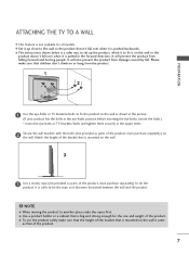
...over when it becomes horizontal between the wall and the product. ! It will prevent the product from the product. 1 2 PREPARATION 1 Use the eye-bolts or TV brackets/bolts to fix the product to the wall so the product doesn't fall over when it on the wall. 3 3 Use a sturdy rope (not provided.... (If your product has the bolts in the eye-bolts position before inserting the eye-bolts, loosen the bolts.) * Insert the eye-bolts or TV brackets/bolts and tighten them securely in the forward direction. Please make sure that the height of the bracket that is mounted on the wall...
...over when it becomes horizontal between the wall and the product. ! It will prevent the product from the product. 1 2 PREPARATION 1 Use the eye-bolts or TV brackets/bolts to fix the product to the wall so the product doesn't fall over when it on the wall. 3 3 Use a sturdy rope (not provided.... (If your product has the bolts in the eye-bolts position before inserting the eye-bolts, loosen the bolts.) * Insert the eye-bolts or TV brackets/bolts and tighten them securely in the forward direction. Please make sure that the height of the bracket that is mounted on the wall...
Owner's Manual (English)
Page 11
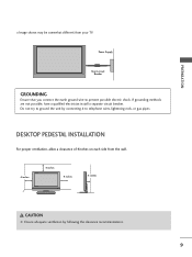
... are not possible, have a qualified electrician install a separate circuit breaker. DESKTOP PEDESTAL INSTALLATION For proper ventilation, allow a clearance of 4inches on each side from your TV. Do not try to ground the unit by following the clearance recommendations. 9 PREPARATION I Image shown may be somewhat different from the wall. 4 inches 4 inches 4 inches...
... are not possible, have a qualified electrician install a separate circuit breaker. DESKTOP PEDESTAL INSTALLATION For proper ventilation, allow a clearance of 4inches on each side from your TV. Do not try to ground the unit by following the clearance recommendations. 9 PREPARATION I Image shown may be somewhat different from the wall. 4 inches 4 inches 4 inches...
Owner's Manual (English)
Page 13
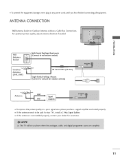
... know when the analogue, cable, and digital programme scans are complete. 11 I If the antenna needs to wall jack for two TV's, install a 2-Way Signal Splitter. ANTENNA CONNECTION Wall Antenna Socket or Outdoor Antenna without a Cable Box Connections. For optimum picture quality..., adjust antenna direction if needed. NOTE G The TV will let you have finished connecting all equipment. I If the antenna is not installed properly, contact your dealer for assistance. ! PREPARATION ...
... know when the analogue, cable, and digital programme scans are complete. 11 I If the antenna needs to wall jack for two TV's, install a 2-Way Signal Splitter. ANTENNA CONNECTION Wall Antenna Socket or Outdoor Antenna without a Cable Box Connections. For optimum picture quality..., adjust antenna direction if needed. NOTE G The TV will let you have finished connecting all equipment. I If the antenna is not installed properly, contact your dealer for assistance. ! PREPARATION ...
Owner's Manual (English)
Page 14
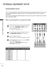
... set -top box. If connected to the COMPONENT IN VIDEO 1 jacks on the remote control. EXTERNAL EQUIPMENT SETUP HD RECEIVER SETUP This TV can receive Digital Over-the-air/Cable signals without an external digital set -top box or other digital external device, refer to the figure... OUT Match the jack colors 1 (DVI) (Y = green, PB = blue, and PR = red) 2 Connect the audio output of the digital2 set . This TV supports HDCP (High-bandwidth Digital Contents Protection) protocol for the digital set-top box.) 4 Select Component 1 input source using the INPUT button on the set...
... set -top box. If connected to the COMPONENT IN VIDEO 1 jacks on the remote control. EXTERNAL EQUIPMENT SETUP HD RECEIVER SETUP This TV can receive Digital Over-the-air/Cable signals without an external digital set -top box or other digital external device, refer to the figure... OUT Match the jack colors 1 (DVI) (Y = green, PB = blue, and PR = red) 2 Connect the audio output of the digital2 set . This TV supports HDCP (High-bandwidth Digital Contents Protection) protocol for the digital set-top box.) 4 Select Component 1 input source using the INPUT button on the set...
Owner's Manual (English)
Page 17
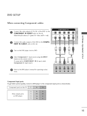
... remote control. If connected to COMPONENT IN 2 input, select Component 2 input source. 5 Refer to the component input ports as shown below. Component ports on the TV Y PB PR Video output ports on the set . EXTERNAL EQUIPMENT SETUP 1 2 Y PB PR L R Component Input ports To get better picture quality, connect a DVD player to...
... remote control. If connected to COMPONENT IN 2 input, select Component 2 input source. 5 Refer to the component input ports as shown below. Component ports on the TV Y PB PR Video output ports on the set . EXTERNAL EQUIPMENT SETUP 1 2 Y PB PR L R Component Input ports To get better picture quality, connect a DVD player to...
Owner's Manual (English)
Page 20
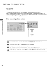
... phenomenon is used; I To avoid picture noise (interference), leave an adequate distance between the VCR and TV. the fixed images on the sides of the VCR. 3 Set VCR output switch to 3 or 4 and then tune TV to the VCR owner's manual.) 18 When connecting with an antenna HDMI/DVI IN 2 1 (DVI) RGB...
... phenomenon is used; I To avoid picture noise (interference), leave an adequate distance between the VCR and TV. the fixed images on the sides of the VCR. 3 Set VCR output switch to 3 or 4 and then tune TV to the VCR owner's manual.) 18 When connecting with an antenna HDMI/DVI IN 2 1 (DVI) RGB...
Owner's Manual (English)
Page 21
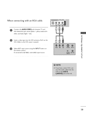
...) DIGITAL AUDIO OUT COMPONENT IN 2 When connecting with an RCA cable 1 (DVI) VIDEO AUDIO AUDIO S-VIDEO VIDEO (MONO) AUDIO 1 Connect the AUDIO/VIDEO jacks between TV and VCR. VIDEO L R S-VIDEO ANT IN OUTPUT ANT OUT SWITCH HDMI/DVI IN 2 1 (DVI) RGB IN RGB (PC) COMPONENT IN VIDEO AUDIO ANTENNA IN DIGITAL...
...) DIGITAL AUDIO OUT COMPONENT IN 2 When connecting with an RCA cable 1 (DVI) VIDEO AUDIO AUDIO S-VIDEO VIDEO (MONO) AUDIO 1 Connect the AUDIO/VIDEO jacks between TV and VCR. VIDEO L R S-VIDEO ANT IN OUTPUT ANT OUT SWITCH HDMI/DVI IN 2 1 (DVI) RGB IN RGB (PC) COMPONENT IN VIDEO AUDIO ANTENNA IN DIGITAL...
Owner's Manual (English)
Page 23
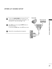
If connected to AV IN1 input, select AV1 input source. S-VIDEO 1 VIDEO L/MONO AUDIO R AV IN 2 21 Match the jack colours.(Video = yel- EXTERNAL EQUIPMENT SETUP OTHER A/V SOURCE SETUP 1 Connect the AUDIO/VIDEO jacks between TV and external equipment. VIDEO L R 3 Operate the corresponding external equipment. low, Audio Left = white, and Audio Right = red) Camcorder Video Game Set 2 Select AV2 input source using the INPUT button on the remote control.
If connected to AV IN1 input, select AV1 input source. S-VIDEO 1 VIDEO L/MONO AUDIO R AV IN 2 21 Match the jack colours.(Video = yel- EXTERNAL EQUIPMENT SETUP OTHER A/V SOURCE SETUP 1 Connect the AUDIO/VIDEO jacks between TV and external equipment. VIDEO L R 3 Operate the corresponding external equipment. low, Audio Left = white, and Audio Right = red) Camcorder Video Game Set 2 Select AV2 input source using the INPUT button on the remote control.
Owner's Manual (English)
Page 24
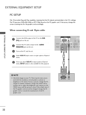
... not be noise associated with the resolution, vertical pattern, contrast or brightness in PC mode. If necessary, change the refresh rate to the TV's settings. If the refresh rate of Special menu, INPUT button is also available for the graphic card accordingly. VIDEO 3AUDIOTurn on the PC ... . RGB OUTPUT AUDIO 22 NOTE G Check the image on the PC graphic card. EXTERNAL EQUIPMENT SETUP EXTERNAL EQUIPMENT SETUP PC SETUP This TV provides Plug and Play capability, meaning that the PC adjusts automatically to another rate or adjust the brightness and contrast on the VIDEO menu ...
... not be noise associated with the resolution, vertical pattern, contrast or brightness in PC mode. If necessary, change the refresh rate to the TV's settings. If the refresh rate of Special menu, INPUT button is also available for the graphic card accordingly. VIDEO 3AUDIOTurn on the PC ... . RGB OUTPUT AUDIO 22 NOTE G Check the image on the PC graphic card. EXTERNAL EQUIPMENT SETUP EXTERNAL EQUIPMENT SETUP PC SETUP This TV provides Plug and Play capability, meaning that the PC adjusts automatically to another rate or adjust the brightness and contrast on the VIDEO menu ...
Owner's Manual (English)
Page 26
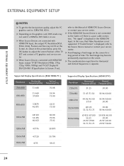
... connection, "No signal" is separate. G When Source Devices are connected with HDMI/DVI Input, output TV SET Resolution (480p, 576p, 720p, 1080i, 1080p) and TV SET Display fit EIA/CEA-861-B Specification to Screen. G Depending on the screen for Horizontal and Vertical...1920x1080i 28.125 33.72/33.75 50.00 59.94/60.00 1920x1080p 67.432/67.500 56.25 26.97/27.00 33.71/33.75 59.939/60.00 50.00 23.97/24.00 29.97/...To get the the best picture quality, adjust the PC graphics card to the Manual of the TV SET and contact a PC graphics card service center. If not, refer to 1280x768, 60Hz.
... connection, "No signal" is separate. G When Source Devices are connected with HDMI/DVI Input, output TV SET Resolution (480p, 576p, 720p, 1080i, 1080p) and TV SET Display fit EIA/CEA-861-B Specification to Screen. G Depending on the screen for Horizontal and Vertical...1920x1080i 28.125 33.72/33.75 50.00 59.94/60.00 1920x1080p 67.432/67.500 56.25 26.97/27.00 33.71/33.75 59.939/60.00 50.00 23.97/24.00 29.97/...To get the the best picture quality, adjust the PC graphics card to the Manual of the TV SET and contact a PC graphics card service center. If not, refer to 1280x768, 60Hz.
Owner's Manual (English)
Page 28
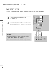
...recording. 1 VIDEO L R S-VIDEO EXTERNAL EQUIPMENT SETUP 26 EXTERNAL EQUIPMENT SETUP AV OUTPUT SETUP The TV has a special signal output capability which allows you to the TV's AV OUT jacks. COMPONENT IN 2 2 See the Operating Manual of the second TV or monitor for fur1th(DeVrI) details regarding that device...'s input settings. AV IN 1 AV OUT HDMI/DVI IN RGB IN RGB (PC) 1 Connect the second TV or monitor to hook up a second TV or monitor. VIDEO AUDIO REMOTE ONTROL IN DIGITAL AUDIO OUT OPTICAL VIDEO RS-232C IN NTROL & SERVICE) AUDIO IDEO VIDEO (...
...recording. 1 VIDEO L R S-VIDEO EXTERNAL EQUIPMENT SETUP 26 EXTERNAL EQUIPMENT SETUP AV OUTPUT SETUP The TV has a special signal output capability which allows you to the TV's AV OUT jacks. COMPONENT IN 2 2 See the Operating Manual of the second TV or monitor for fur1th(DeVrI) details regarding that device...'s input settings. AV IN 1 AV OUT HDMI/DVI IN RGB IN RGB (PC) 1 Connect the second TV or monitor to hook up a second TV or monitor. VIDEO AUDIO REMOTE ONTROL IN DIGITAL AUDIO OUT OPTICAL VIDEO RS-232C IN NTROL & SERVICE) AUDIO IDEO VIDEO (...
Owner's Manual (English)
Page 29
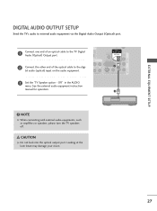
...VIDEO RS-232C IN (CONTROL & SERVICE) 1 AUDIO S-VIDEO VIDEO (MONO) AUDIO 3 Set the "TV Speaker option - NOTE G When connecting with external audio equipments, such as amplifiers or speakers, please turn the TV speakers off. See the external audio equipment instruction manual for operation. 2 ! Looking at the laser beam... may damage your vision. 27 Off" in the AUDIO menu. AV OUT AV IN 1 EXTERNAL EQUIPMENT SETUP DIGITAL AUDIO OUTPUT SETUP Send the TV's audio to the digi- CAUTION G Do not look into the optical output port. RGB IN HDMI/DVI IN 1 Connect one end of ...
...VIDEO RS-232C IN (CONTROL & SERVICE) 1 AUDIO S-VIDEO VIDEO (MONO) AUDIO 3 Set the "TV Speaker option - NOTE G When connecting with external audio equipments, such as amplifiers or speakers, please turn the TV speakers off. See the external audio equipment instruction manual for operation. 2 ! Looking at the laser beam... may damage your vision. 27 Off" in the AUDIO menu. AV OUT AV IN 1 EXTERNAL EQUIPMENT SETUP DIGITAL AUDIO OUTPUT SETUP Send the TV's audio to the digi- CAUTION G Do not look into the optical output port. RGB IN HDMI/DVI IN 1 Connect one end of ...
Owner's Manual (English)
Page 30
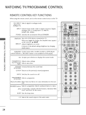
...3 4 5 6 7 8 9 APM 0 SLEEP SIZE ? VOLUME Increase/decrease the sound level. PROGRAMME UP/DOWN Selects a programme. It returns to TV. THUMBSTICK Adjusts menu settings. (Up/Down/Left Right) Selects menu item. APM Concurrently, compare with the Dynamic, Standard, Mild, User1 and User2 on... players control buttons ("RECORD" button is not available for DVD player). D/A INPUT Selects digital or analogue mode. (Digital TV / Analogue TV) INPUT External input modes rotate in a menu. SIMPLINK See a list of screen information to the previously viewed programme. ...
...3 4 5 6 7 8 9 APM 0 SLEEP SIZE ? VOLUME Increase/decrease the sound level. PROGRAMME UP/DOWN Selects a programme. It returns to TV. THUMBSTICK Adjusts menu settings. (Up/Down/Left Right) Selects menu item. APM Concurrently, compare with the Dynamic, Standard, Mild, User1 and User2 on... players control buttons ("RECORD" button is not available for DVD player). D/A INPUT Selects digital or analogue mode. (Digital TV / Analogue TV) INPUT External input modes rotate in a menu. SIMPLINK See a list of screen information to the previously viewed programme. ...
Owner's Manual (English)
Page 31
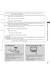
GUIDE Shows a programme schedule. BUTTONS Text button is used to operate external devices. WATCHING TV/PROGRAMME CONTROL TV, VCR, DVD Selects the remote operating mode: TV, VCR, DVD. Select other operating modes, for the remote to enable teletext services while other buttons are for teletext....picture format. I Close cover. INPUT D/A INPUT POWER SIMPLINK BRIGHT MODE TV VCR DVD RATIO TEXT INFO GUIDE I Use a remote control up to TV viewing from any menu. I Open the battery compartment cover on the TV screen in the case of used for teletext functions. * For further ...
GUIDE Shows a programme schedule. BUTTONS Text button is used to operate external devices. WATCHING TV/PROGRAMME CONTROL TV, VCR, DVD Selects the remote operating mode: TV, VCR, DVD. Select other operating modes, for the remote to enable teletext services while other buttons are for teletext....picture format. I Close cover. INPUT D/A INPUT POWER SIMPLINK BRIGHT MODE TV VCR DVD RATIO TEXT INFO GUIDE I Use a remote control up to TV viewing from any menu. I Open the battery compartment cover on the TV screen in the case of used for teletext functions. * For further ...
Owner's Manual (English)
Page 32
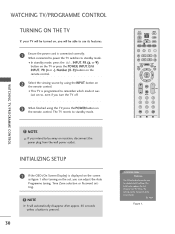
...Ensure the power cord is programmed to remember which mode it was last set , you can be changed in menu once entered. I This TV is connected correctly. Next Figure 1. INITIALIZING SETUP 1 If the OSD (On Screen Display) is pressed. 30 Installation Guide Welcome The Following ... MENU EXIT LIST FAV OK VOL Q.VIEW PR PAGE MUTE 1 2 3 4 5 6 7 8 9 APM 0 SLEEP WATCHING TV/PROGRAMME CONTROL ! WATCHING TV/PROGRAMME CONTROL TURNING ON THE TV If your TV will be turned on, you will automatically disappear after approx. 40 seconds unless a button is displayed on the screen as...
...Ensure the power cord is programmed to remember which mode it was last set , you can be changed in menu once entered. I This TV is connected correctly. Next Figure 1. INITIALIZING SETUP 1 If the OSD (On Screen Display) is pressed. 30 Installation Guide Welcome The Following ... MENU EXIT LIST FAV OK VOL Q.VIEW PR PAGE MUTE 1 2 3 4 5 6 7 8 9 APM 0 SLEEP WATCHING TV/PROGRAMME CONTROL ! WATCHING TV/PROGRAMME CONTROL TURNING ON THE TV If your TV will be turned on, you will automatically disappear after approx. 40 seconds unless a button is displayed on the screen as...

Owner's Manual (English)
Page 33
... - or NUMBER buttons to switch the sound off, press the MUTE button. VOL Q.VIEW PR PAGE MUTE 1 2 3 4 5 6 7 8 9 APM 0 SLEEP SIZE ? REVEAL INDEX I/II TIME WATCHING TV/PROGRAMME CONTROL VOLUME ADJUSTMENT Adjust the volume to suit your personal preference. 1 Press the VOL + or - INPUT D/A INPUT POWER SIMPLINK BRIGHT MODE...
... - or NUMBER buttons to switch the sound off, press the MUTE button. VOL Q.VIEW PR PAGE MUTE 1 2 3 4 5 6 7 8 9 APM 0 SLEEP SIZE ? REVEAL INDEX I/II TIME WATCHING TV/PROGRAMME CONTROL VOLUME ADJUSTMENT Adjust the volume to suit your personal preference. 1 Press the VOL + or - INPUT D/A INPUT POWER SIMPLINK BRIGHT MODE...


