Instruction Manual
Page 1
... Only Register Online Register your records Record the serial number, found on the back of the unit, in the space provided below. KAC-X812D SUBWOOFER POWER AMPLIFIER 7 page 2-9 INSTRUCTION MANUAL AMPLIFICATEUR DE PUISSANCE DU SUBWOOFER 7 page 10-17 MODE D'EMPLOI AMPLIFICADOR DE POTENCIA DEL ALTAVOZ DE SONIDO ENVOLVENTE... spaces designated on the product. Familiarity with installation and operation procedures will help you call upon your new power amplifier. Refer to read through this instruction manual. For your Kenwood product at www.kenwoodusa.com © B64-3393-00/00 (KV)
... Only Register Online Register your records Record the serial number, found on the back of the unit, in the space provided below. KAC-X812D SUBWOOFER POWER AMPLIFIER 7 page 2-9 INSTRUCTION MANUAL AMPLIFICATEUR DE PUISSANCE DU SUBWOOFER 7 page 10-17 MODE D'EMPLOI AMPLIFICADOR DE POTENCIA DEL ALTAVOZ DE SONIDO ENVOLVENTE... spaces designated on the product. Familiarity with installation and operation procedures will help you call upon your new power amplifier. Refer to read through this instruction manual. For your Kenwood product at www.kenwoodusa.com © B64-3393-00/00 (KV)
Instruction Manual
Page 2
... soft cloth. 2 CAUTION Do not wipe the panel with the prescribed rating. Informations When the inside the unit. • If the unit starts to the amplifier. 4Ω 4Ω 8 Ω 4Ω 4Ω 2 Ω Combined impedance 2 English When voltage gets out of the speakers that are going...and damage to protect the unit and speakers from various problems. When Protection operates, the display informs you experience problems during installation, consult your Kenwood dealer. • Do not touch the unit during use a new one with a hard cloth or a cloth dampened by volatile solvents ...
... soft cloth. 2 CAUTION Do not wipe the panel with the prescribed rating. Informations When the inside the unit. • If the unit starts to the amplifier. 4Ω 4Ω 8 Ω 4Ω 4Ω 2 Ω Combined impedance 2 English When voltage gets out of the speakers that are going...and damage to protect the unit and speakers from various problems. When Protection operates, the display informs you experience problems during installation, consult your Kenwood dealer. • Do not touch the unit during use a new one with a hard cloth or a cloth dampened by volatile solvents ...
Instruction Manual
Page 3
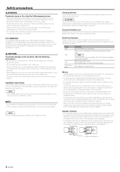
... installed, do not place any object on the opposite side such as the brake lamps, turn signal lamps and windshield wipers operate normally. Install the amplifier in a place where people, resins, and other damage. • Do not install near the dashboard, rear tray, or air bag safety parts. • ... grounding wire following this unit in the vehicle, check that there is nothing hazardous on top of the unit. • The surface temperature of the amplifier will not come into contact with driving, In a location that gets wet, In a dusty location, In a place that gets hot, In a place that ...
... installed, do not place any object on the opposite side such as the brake lamps, turn signal lamps and windshield wipers operate normally. Install the amplifier in a place where people, resins, and other damage. • Do not install near the dashboard, rear tray, or air bag safety parts. • ... grounding wire following this unit in the vehicle, check that there is nothing hazardous on top of the unit. • The surface temperature of the amplifier will not come into contact with driving, In a location that gets wet, In a dusty location, In a place that gets hot, In a place that ...
Instruction Manual
Page 4
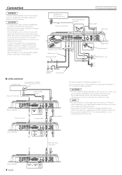
... R) 90 1 901 901 901 90 1 901 901 Battery Ground wire* ■ LX-Bus connection CENTER UNIT To Kenwood disc changer/ External optional accessory Power control wire Control cable (option) 30 30 Master amplifier Extension wire* 456 "0" 4 5 6 ID NUMBER S-video cable* 23 23 78 78 RCA cable* Set the ID... can cause this limit, you cannot control amps from the Center Unit. • If you assign the same ID number to multiple amplifiers, they malfunction when you operate any of them from unconnected wires or connectors to prevent short circuits. • Connect the speaker wires ...
... R) 90 1 901 901 901 90 1 901 901 Battery Ground wire* ■ LX-Bus connection CENTER UNIT To Kenwood disc changer/ External optional accessory Power control wire Control cable (option) 30 30 Master amplifier Extension wire* 456 "0" 4 5 6 ID NUMBER S-video cable* 23 23 78 78 RCA cable* Set the ID... can cause this limit, you cannot control amps from the Center Unit. • If you assign the same ID number to multiple amplifiers, they malfunction when you operate any of them from unconnected wires or connectors to prevent short circuits. • Connect the speaker wires ...
Instruction Manual
Page 5
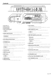
...control This control adjusts the frequency band output from this switch is reversed. & BRF (band reject filter) switch When this unit. @1 B.R.F. NOTE Amplifier control is possible even while OFF. ^ PHASE switch When this switch is set "180°" (Reverse) the speaker output phase is set to...the Center Unit and turn it with all the systems. 5 Speaker output terminals As this unit accepts speakers with a minimum impedance of the amplifier. This improves the reproduction performance of the unit. Assign ID Numbers "1" to "7" to these numbers. The indicator flashes several seconds when ...
...control This control adjusts the frequency band output from this switch is reversed. & BRF (band reject filter) switch When this unit. @1 B.R.F. NOTE Amplifier control is possible even while OFF. ^ PHASE switch When this switch is set "180°" (Reverse) the speaker output phase is set to...the Center Unit and turn it with all the systems. 5 Speaker output terminals As this unit accepts speakers with a minimum impedance of the amplifier. This improves the reproduction performance of the unit. Assign ID Numbers "1" to "7" to these numbers. The indicator flashes several seconds when ...
Instruction Manual
Page 6
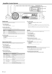
...Indicates the internal temperature (°F/°C). The setup items and set to its default Press the [3] button for at least 2 seconds. To call the Amplifier Control's values, hold down the [2] button 3 or more seconds during ID number display ("AMP"). Message "----" is displayed, and the value is ... Enter Menu mode Press the [MENU] button. 2 Select the Menu item Press the [MENU] button. Separate Amp Control You can control sounds using the Amplifier Control function of the cooling fan in 3 steps: "FAST", "SLOW" or "OFF". 3 Exit Menu mode Press the [MENU] button for at least...
...Indicates the internal temperature (°F/°C). The setup items and set to its default Press the [3] button for at least 2 seconds. To call the Amplifier Control's values, hold down the [2] button 3 or more seconds during ID number display ("AMP"). Message "----" is displayed, and the value is ... Enter Menu mode Press the [MENU] button. 2 Select the Menu item Press the [MENU] button. Separate Amp Control You can control sounds using the Amplifier Control function of the cooling fan in 3 steps: "FAST", "SLOW" or "OFF". 3 Exit Menu mode Press the [MENU] button for at least...
Instruction Manual
Page 7
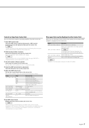
... number of the amp you cannot operate the set items. 3 Set an ID number of Amp to ON, low frequency response is generated to the Kenwood's dealership. Display Informations "AMP × E-01"/"AMP × COND E-01" When the inside of the unit is displayed and you use the Amp ...". NOTE When you have controlled the bass or treble of the sound using the Equalizer or DSP function of the Center Unit, and when you amplify the same frequency as follows. "CURR" Indicates the current consumption (A). "AMP × E-02"/"AMP × COND E-02" NOTE Turn the POWER switch Off and...
... number of the amp you cannot operate the set items. 3 Set an ID number of Amp to ON, low frequency response is generated to the Kenwood's dealership. Display Informations "AMP × E-01"/"AMP × COND E-01" When the inside of the unit is displayed and you use the Amp ...". NOTE When you have controlled the bass or treble of the sound using the Equalizer or DSP function of the Center Unit, and when you amplify the same frequency as follows. "CURR" Indicates the current consumption (A). "AMP × E-02"/"AMP × COND E-02" NOTE Turn the POWER switch Off and...
Instruction Manual
Page 8
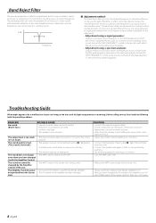
... The speaker cord is pinched by a screw in the car body. • The switches may just be changed the ID number of an amplifier, turn it On again. 8 English Before calling service, first check the following table for possible problems. PROBLEM No sound. (Blown fuse.) ...Frequency ■ Adjustment method: The band reject filter cuts only the limited frequencies to the position with a fine frequency measurement capability for the Master amplifier. The sound does not change • The AMP CONT has been turned "OFF". SOLUTION • Connect the input (or output) cables. ...
... The speaker cord is pinched by a screw in the car body. • The switches may just be changed the ID number of an amplifier, turn it On again. 8 English Before calling service, first check the following table for possible problems. PROBLEM No sound. (Blown fuse.) ...Frequency ■ Adjustment method: The band reject filter cuts only the limited frequencies to the position with a fine frequency measurement capability for the Master amplifier. The sound does not change • The AMP CONT has been turned "OFF". SOLUTION • Connect the input (or output) cables. ...
Instruction Manual
Page 9
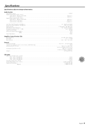
... (variable) Frequency Response (+ 0 , - 3 dB)...5 Hz - 200 Hz Signal to Noise Ratio...100 dB Sensitivity (rated output) (MAX.) ...0.2 V Sensitivity (rated output) (MIN.) ...5.0 V Input Impedance ...10 kΩ Amplifier Control Section (EQ) Bass frequency ...60 / 80 / 100 / 200 Hz Bass level ...-15 - +15 dB Bass Q factor...1.00 / 1.25 / 1.50 / 2.00 General Operating Voltage ...14...
... (variable) Frequency Response (+ 0 , - 3 dB)...5 Hz - 200 Hz Signal to Noise Ratio...100 dB Sensitivity (rated output) (MAX.) ...0.2 V Sensitivity (rated output) (MIN.) ...5.0 V Input Impedance ...10 kΩ Amplifier Control Section (EQ) Bass frequency ...60 / 80 / 100 / 200 Hz Bass level ...-15 - +15 dB Bass Q factor...1.00 / 1.25 / 1.50 / 2.00 General Operating Voltage ...14...


