Instruction Manual
Page 1
... service on the warranty card, and in the space provided below. Refer to read through this instruction manual. KAC-X812D SUBWOOFER POWER AMPLIFIER 7 page 2-9 INSTRUCTION MANUAL AMPLIFICATEUR DE PUISSANCE DU SUBWOOFER 7 page 10-17 MODE D'EMPLOI AMPLIFICADOR DE POTENCIA DEL ALTAVOZ DE SONIDO ENVOLVENTE 7 página 18-25 MANUAL DE INSTRUCCIONES Take the time to the model and serial numbers whenever you obtain the best performance from your Kenwood...
... service on the warranty card, and in the space provided below. Refer to read through this instruction manual. KAC-X812D SUBWOOFER POWER AMPLIFIER 7 page 2-9 INSTRUCTION MANUAL AMPLIFICATEUR DE PUISSANCE DU SUBWOOFER 7 page 10-17 MODE D'EMPLOI AMPLIFICADOR DE POTENCIA DEL ALTAVOZ DE SONIDO ENVOLVENTE 7 página 18-25 MANUAL DE INSTRUCCIONES Take the time to the model and serial numbers whenever you obtain the best performance from your Kenwood...
Instruction Manual
Page 2
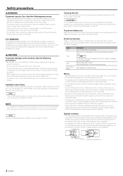
... ground wire to a metal part of them at a time. Protection function There is not connected. • Be sure to be working right, consult your Kenwood dealer. Informations When the inside the unit. • If the unit starts to emit smoke or strange smells, turn the power on if the ground wire is a Protection function installed in the power cord near the battery. When more than the maximum output power (in the instruction manual...
... ground wire to a metal part of them at a time. Protection function There is not connected. • Be sure to be working right, consult your Kenwood dealer. Informations When the inside the unit. • If the unit starts to emit smoke or strange smells, turn the power on if the ground wire is a Protection function installed in the power cord near the battery. When more than the maximum output power (in the instruction manual...
Instruction Manual
Page 3
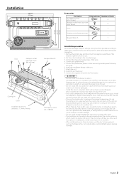
... 252 mm 265 mm Accessories Part name Self-tapping screws (ø5 × 18 mm) Hexagon socket head cap screw (M4 × 8 mm) External View Number of Items 4 4 Cover 1 Terminal cover (Power terminal) 1 Hexagon Wrench 1 Installation procedure Since there are large variety of the units. 4. Connect the input and output wires of settings and connections possible according to applications, read the instruction manual well to make sure that gets hit...
... 252 mm 265 mm Accessories Part name Self-tapping screws (ø5 × 18 mm) Hexagon socket head cap screw (M4 × 8 mm) External View Number of Items 4 4 Cover 1 Terminal cover (Power terminal) 1 Hexagon Wrench 1 Installation procedure Since there are large variety of the units. 4. Connect the input and output wires of settings and connections possible according to applications, read the instruction manual well to make sure that gets hit...
Instruction Manual
Page 4
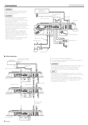
... wipers work properly. * Commercially available parts CENTER UNIT (CD receiver, etc.) Power control wire RCA cable ground terminal GND RCA cable* Left input 78 30 30 Terminal cover Battery wire* Protective Fuse* 23 456 Right input Lead terminal* Subwoofer (L + R) 90 1 901 901 901 90 1 901 901 Battery Ground wire* ■ LX-Bus connection CENTER UNIT To Kenwood disc changer/ External optional accessory Power control wire Control cable (option) 30 30 Master amplifier Extension wire* 456 "0" 4 5 6 ID NUMBER S-video cable* 23 23 78 78 RCA cable* Set the ID number of...
... wipers work properly. * Commercially available parts CENTER UNIT (CD receiver, etc.) Power control wire RCA cable ground terminal GND RCA cable* Left input 78 30 30 Terminal cover Battery wire* Protective Fuse* 23 456 Right input Lead terminal* Subwoofer (L + R) 90 1 901 901 901 90 1 901 901 Battery Ground wire* ■ LX-Bus connection CENTER UNIT To Kenwood disc changer/ External optional accessory Power control wire Control cable (option) 30 30 Master amplifier Extension wire* 456 "0" 4 5 6 ID NUMBER S-video cable* 23 23 78 78 RCA cable* Set the ID number of...
Instruction Manual
Page 5
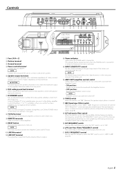
...; 2) 2 Battery terminal 3 Ground terminal 4 Power control terminal Controls the unit ON/OFF. Otherwise malfunction may result. 6 RCA cable ground lead terminal When using an RCA cable with a ground lead attached, connect the ground lead to connect it as Slave amplifiers. Do not duplicate these terminals. 2 CAUTION The rated input of the speakers should be used for amplifier control from the line input terminal is output. 1 # Power indicator Lights when the POWER switch is set to "-6dB"/"-12dB", frequencies in the instruction manual of the center unit. % AMP CONT (amplifier control...
...; 2) 2 Battery terminal 3 Ground terminal 4 Power control terminal Controls the unit ON/OFF. Otherwise malfunction may result. 6 RCA cable ground lead terminal When using an RCA cable with a ground lead attached, connect the ground lead to connect it as Slave amplifiers. Do not duplicate these terminals. 2 CAUTION The rated input of the speakers should be used for amplifier control from the line input terminal is output. 1 # Power indicator Lights when the POWER switch is set to "-6dB"/"-12dB", frequencies in the instruction manual of the center unit. % AMP CONT (amplifier control...
Instruction Manual
Page 6
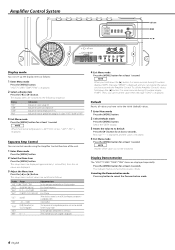
... least 2 seconds. Indicates the internal temperature (°F/°C). To call the Amplifier Control's values, hold down the [2] button 3 or more seconds during ID number display ("AMP"). Canceling the Demonstration mode Press any button to The ID Number you have set values are switched as follows: 1 Enter Menu mode Press the [MENU] button. Display Range "VOLT"/"CURR"/"TEMP"/"FAN" "BASS" 60/80...
... least 2 seconds. Indicates the internal temperature (°F/°C). To call the Amplifier Control's values, hold down the [2] button 3 or more seconds during ID number display ("AMP"). Canceling the Demonstration mode Press any button to The ID Number you have set values are switched as follows: 1 Enter Menu mode Press the [MENU] button. Display Range "VOLT"/"CURR"/"TEMP"/"FAN" "BASS" 60/80...
Instruction Manual
Page 7
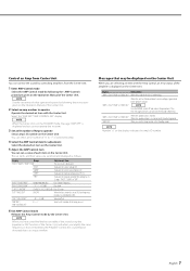
... display indicates the amp's ID number. "FAN" Indicates the rotation speed of the cooling fan in the Standby mode. NOTE When you have controlled the bass or treble of the sound using the Equalizer or DSP function of connected amps. 4 Select the AMP Control item for adjustment Select the desired set item on the Center Unit. "AMP × E-02"/"AMP × COND E-02" NOTE Turn the POWER switch Off and release the protection. "AMP...
... display indicates the amp's ID number. "FAN" Indicates the rotation speed of the cooling fan in the Standby mode. NOTE When you have controlled the bass or treble of the sound using the Equalizer or DSP function of connected amps. 4 Select the AMP Control item for adjustment Select the desired set item on the Center Unit. "AMP × E-02"/"AMP × COND E-02" NOTE Turn the POWER switch Off and release the protection. "AMP...
Instruction Manual
Page 8
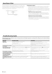
... the 9 / · of the terminals and wires well. • Connect the speaker wire again so that it eliminates only the frequencies causing resonance or standing waves. 0 dB Frequency ■ Adjustment method: The band reject filter cuts only the limited frequencies to standing waves at certain frequencies. The output level is used . The sound does not change • The AMP CONT has been turned "OFF". Unit. Troubleshooting Guide What might appear to...
... the 9 / · of the terminals and wires well. • Connect the speaker wire again so that it eliminates only the frequencies causing resonance or standing waves. 0 dB Frequency ■ Adjustment method: The band reject filter cuts only the limited frequencies to standing waves at certain frequencies. The output level is used . The sound does not change • The AMP CONT has been turned "OFF". Unit. Troubleshooting Guide What might appear to...
Instruction Manual
Page 9
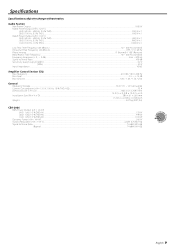
... (rated output) (MIN.) ...5.0 V Input Impedance ...10 kΩ Amplifier Control Section (EQ) Bass frequency ...60 / 80 / 100 / 200 Hz Bass level ...-15 - +15 dB Bass Q factor...1.00 / 1.25 / 1.50 / 2.00 General Operating Voltage ...14.4 V (11 - 16 V allowable) Current Consumption (+B = 12.0 V, 100 Hz, 10 % THD, 4 Ω)...55 A Dimensions (W × H × D) ...386 × 61 × 259.5 mm ...15-3/16 × 2-3/8 × 10-3/16 inch Installation Size...
... (rated output) (MIN.) ...5.0 V Input Impedance ...10 kΩ Amplifier Control Section (EQ) Bass frequency ...60 / 80 / 100 / 200 Hz Bass level ...-15 - +15 dB Bass Q factor...1.00 / 1.25 / 1.50 / 2.00 General Operating Voltage ...14.4 V (11 - 16 V allowable) Current Consumption (+B = 12.0 V, 100 Hz, 10 % THD, 4 Ω)...55 A Dimensions (W × H × D) ...386 × 61 × 259.5 mm ...15-3/16 × 2-3/8 × 10-3/16 inch Installation Size...


