Instruction Manual
Page 1
...-3393-00/00 (KV) Familiarity with installation and operation procedures will help you call upon your Kenwood dealer for information or service on the warranty card, and in the spaces designated on the product. KAC-X812D SUBWOOFER POWER AMPLIFIER 7 page 2-9 INSTRUCTION MANUAL AMPLIFICATEUR DE PUISSANCE DU SUBWOOFER 7 page 10-17 MODE D'EMPLOI AMPLIFICADOR DE POTENCIA...
...-3393-00/00 (KV) Familiarity with installation and operation procedures will help you call upon your Kenwood dealer for information or service on the warranty card, and in the spaces designated on the product. KAC-X812D SUBWOOFER POWER AMPLIFIER 7 page 2-9 INSTRUCTION MANUAL AMPLIFICATEUR DE PUISSANCE DU SUBWOOFER 7 page 10-17 MODE D'EMPLOI AMPLIFICADOR DE POTENCIA...
Instruction Manual
Page 2
...installation, consult your Kenwood dealer. • If the unit does not seem to be working right, consult your Kenwood dealer. When the unit has failed and direct current voltage is in contact with a diameter of 8 mm² (AWG 8) or greater.) • When more than one power amplifier are less than ...the output power of the Center Unit. When the speaker ...
...installation, consult your Kenwood dealer. • If the unit does not seem to be working right, consult your Kenwood dealer. When the unit has failed and direct current voltage is in contact with a diameter of 8 mm² (AWG 8) or greater.) • When more than one power amplifier are less than ...the output power of the Center Unit. When the speaker ...
Instruction Manual
Page 3
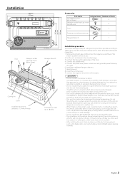
.... Connect the speaker wires. 5. Attach the unit. 8. terminal of the amplifier will not obstruct driving. Connect the input and output wires of the unit are blocked. Connect the negative - Connect the power wire, power control wire and grounding wire following this unit in a location which it may... heat build-up occurs and the unit may cause injury or an accident. • After installing the unit, check to easily dissipate. Install the amplifier in a place where people, resins, and other damage. • Do not install near the dashboard, rear tray, or air bag safety parts....
.... Connect the speaker wires. 5. Attach the unit. 8. terminal of the amplifier will not obstruct driving. Connect the input and output wires of the unit are blocked. Connect the negative - Connect the power wire, power control wire and grounding wire following this unit in a location which it may... heat build-up occurs and the unit may cause injury or an accident. • After installing the unit, check to easily dissipate. Install the amplifier in a place where people, resins, and other damage. • Do not install near the dashboard, rear tray, or air bag safety parts....
Instruction Manual
Page 4
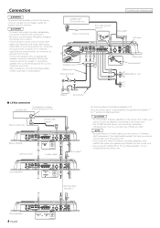
...is not output normally, immediately turn power off and check connections. • Be sure to turn the power off before changing the setting of any of the car can connect up to 7 Slave amplifiers. NOTE • The total length of the Master amplifier to "0". "7" ID NUMBER 23 23... R) 90 1 901 901 901 90 1 901 901 Battery Ground wire* ■ LX-Bus connection CENTER UNIT To Kenwood disc changer/ External optional accessory Power control wire Control cable (option) 30 30 Master amplifier Extension wire* 456 "0" 4 5 6 ID NUMBER S-video cable* 23 23 78 78 RCA cable* Set the ID...
...is not output normally, immediately turn power off and check connections. • Be sure to turn the power off before changing the setting of any of the car can connect up to 7 Slave amplifiers. NOTE • The total length of the Master amplifier to "0". "7" ID NUMBER 23 23... R) 90 1 901 901 901 90 1 901 901 Battery Ground wire* ■ LX-Bus connection CENTER UNIT To Kenwood disc changer/ External optional accessory Power control wire Control cable (option) 30 30 Master amplifier Extension wire* 456 "0" 4 5 6 ID NUMBER S-video cable* 23 23 78 78 RCA cable* Set the ID...
Instruction Manual
Page 5
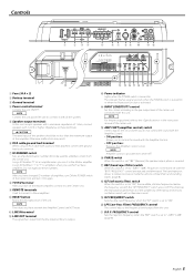
... Sets the rejection frequency when the "BRF" switch is set the Master amplifier, connect it as Slave amplifiers. Controls 78 30 30 1 2 34 456 23 901 5 6 7 89 0 !@ # 1 Fuse (30 A × 2) 2 Battery terminal 3 Ground terminal 4 Power control terminal Controls the unit ON/OFF. Otherwise malfunction may result. 6 ... terminals Used to connect to the pre-output level of the speakers should be used for amplifier control from the Center Unit. The indicator flashes several seconds when the POWER switch is turned On or when the Protection function is turned On. LINE IN terminal @...
... Sets the rejection frequency when the "BRF" switch is set the Master amplifier, connect it as Slave amplifiers. Controls 78 30 30 1 2 34 456 23 901 5 6 7 89 0 !@ # 1 Fuse (30 A × 2) 2 Battery terminal 3 Ground terminal 4 Power control terminal Controls the unit ON/OFF. Otherwise malfunction may result. 6 ... terminals Used to connect to the pre-output level of the speakers should be used for amplifier control from the Center Unit. The indicator flashes several seconds when the POWER switch is turned On or when the Protection function is turned On. LINE IN terminal @...
Instruction Manual
Page 7
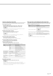
...the Center Unit. 5 Adjust the AMP Control item You can control the sound by controlling amplifiers from the Center Unit. 1 Enter AMP Control mode Select the AMP Control mode by the...Indicates the internal temperature (°F/°C). "AMP × E-02"/"AMP × COND E-02" NOTE Turn the POWER switch Off and release the protection. "AMP × E-03"/"AMP × COND E-03" When the speaker ...; E-01"/"AMP × COND E-01" When the inside of the unit is generated to the Kenwood's dealership. English 7 "FAN" Indicates the rotation speed of the cooling fan in contact with the...
...the Center Unit. 5 Adjust the AMP Control item You can control the sound by controlling amplifiers from the Center Unit. 1 Enter AMP Control mode Select the AMP Control mode by the...Indicates the internal temperature (°F/°C). "AMP × E-02"/"AMP × COND E-02" NOTE Turn the POWER switch Off and release the protection. "AMP × E-03"/"AMP × COND E-03" When the speaker ...; E-01"/"AMP × COND E-01" When the inside of the unit is generated to the Kenwood's dealership. English 7 "FAN" Indicates the rotation speed of the cooling fan in contact with the...
Instruction Manual
Page 8
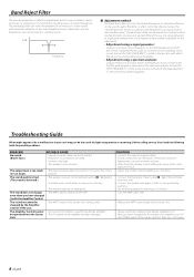
...output) cables are disconnected. • Protection circuit may be activated. • Volume is too high. • The speaker cord is used . The Amplifier Control cannot • An incorrect ID number is shorted. The band reject filter can be adjusted according to what you have changed the ID number... of an amplifier, turn Off the POWER switch of the Center Unit first, then turn it On again. 8 English FREQUENCY" control to find the peak frequency observed on...
...output) cables are disconnected. • Protection circuit may be activated. • Volume is too high. • The speaker cord is used . The Amplifier Control cannot • An incorrect ID number is shorted. The band reject filter can be adjusted according to what you have changed the ID number... of an amplifier, turn Off the POWER switch of the Center Unit first, then turn it On again. 8 English FREQUENCY" control to find the peak frequency observed on...
Instruction Manual
Page 9
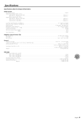
...- 200 Hz Signal to Noise Ratio...100 dB Sensitivity (rated output) (MAX.) ...0.2 V Sensitivity (rated output) (MIN.) ...5.0 V Input Impedance ...10 kΩ Amplifier Control Section (EQ) Bass frequency ...60 / 80 / 100 / 200 Hz Bass level ...-15 - +15 dB Bass Q factor...1.00 / 1.25 / 1.50...16 × 2-3/8 × 10-3/8 inch Weight ...4.07 kg (8.97 lbs) CEA-2006 RMS Power Output (+B = 14.4 V) (4 Ω/ 1ch) (1.0 % THD+N)...533 W (2 Ω/ 1ch) (1.0 % THD+N)...919 W (1 Ω/ 1ch) (1.0 % THD+N)...1016 W Dynamic Power (+B = 14.4 V) ...566 W Output Regulation (+B = 14.4 V)...under 0.2 dB (4 Ω...
...- 200 Hz Signal to Noise Ratio...100 dB Sensitivity (rated output) (MAX.) ...0.2 V Sensitivity (rated output) (MIN.) ...5.0 V Input Impedance ...10 kΩ Amplifier Control Section (EQ) Bass frequency ...60 / 80 / 100 / 200 Hz Bass level ...-15 - +15 dB Bass Q factor...1.00 / 1.25 / 1.50...16 × 2-3/8 × 10-3/8 inch Weight ...4.07 kg (8.97 lbs) CEA-2006 RMS Power Output (+B = 14.4 V) (4 Ω/ 1ch) (1.0 % THD+N)...533 W (2 Ω/ 1ch) (1.0 % THD+N)...919 W (1 Ω/ 1ch) (1.0 % THD+N)...1016 W Dynamic Power (+B = 14.4 V) ...566 W Output Regulation (+B = 14.4 V)...under 0.2 dB (4 Ω...


