Instruction Manual
Page 2
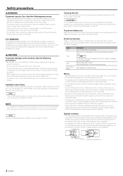
...Unit released in the unit to protect the unit and speakers from the battery. NOTE • The LX AMP and the sensor unit cannot be working right, consult your Kenwood dealer. • Do not touch the unit during use radio frequency energy. NOTE This Class B digital .... They can control this unit directly from various problems. When Protection operates, the display informs you experience problems during installation, consult your Kenwood dealer. • If the unit does not seem to be connected simultaneously. Protection function There is in contact with the vehicle ground....
...Unit released in the unit to protect the unit and speakers from the battery. NOTE • The LX AMP and the sensor unit cannot be working right, consult your Kenwood dealer. • Do not touch the unit during use radio frequency energy. NOTE This Class B digital .... They can control this unit directly from various problems. When Protection operates, the display informs you experience problems during installation, consult your Kenwood dealer. • If the unit does not seem to be connected simultaneously. Protection function There is in contact with the vehicle ground....
Instruction Manual
Page 3
... mm FAN VOLT TEMP CURR 1 150 100 2 0.5 3 70 4 (MIN)5 0.2(MAX) 50 200 INPUT LPF SENSITIVITY(V) FREQUENCY(Hz) 40 200 B.R.F FREQUENCY(Hz) LPF OPERATION 0 200 Hz AMP CONT PHASE BRF ISF ISF FREQUENCY -4 150 Hz 100 Hz ON 180˃ -12dB ON 25Hz -8 70 Hz -12 50 Hz -6dB -16 -20 30...
... mm FAN VOLT TEMP CURR 1 150 100 2 0.5 3 70 4 (MIN)5 0.2(MAX) 50 200 INPUT LPF SENSITIVITY(V) FREQUENCY(Hz) 40 200 B.R.F FREQUENCY(Hz) LPF OPERATION 0 200 Hz AMP CONT PHASE BRF ISF ISF FREQUENCY -4 150 Hz 100 Hz ON 180˃ -12dB ON 25Hz -8 70 Hz -12 50 Hz -6dB -16 -20 30...
Instruction Manual
Page 4
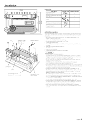
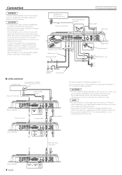
...Right input Lead terminal* Subwoofer (L + R) 90 1 901 901 901 90 1 901 901 Battery Ground wire* ■ LX-Bus connection CENTER UNIT To Kenwood disc changer/ External optional accessory Power control wire Control cable (option) 30 30 Master amplifier Extension wire* 456 "0" 4 5 6 ID NUMBER S-video cable...* 23 23 78 78 RCA cable* Set the ID number of the car can cause this limit, you cannot control amps from the Center Unit. • If you operate any of them . 2 CAUTION • Do not connect 2 Master amplifiers to appropriate speaker connectors ...
...Right input Lead terminal* Subwoofer (L + R) 90 1 901 901 901 90 1 901 901 Battery Ground wire* ■ LX-Bus connection CENTER UNIT To Kenwood disc changer/ External optional accessory Power control wire Control cable (option) 30 30 Master amplifier Extension wire* 456 "0" 4 5 6 ID NUMBER S-video cable...* 23 23 78 78 RCA cable* Set the ID number of the car can cause this limit, you cannot control amps from the Center Unit. • If you operate any of them . 2 CAUTION • Do not connect 2 Master amplifiers to appropriate speaker connectors ...
Instruction Manual
Page 5
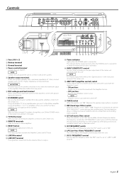
... resonance inside the vehicle compartment and standing waves. (page 8) * ISF (infrasonic filter) switch When this terminal. 7 ID NUMBER switch Sets an amp identification number (ID) to an amplifier when you have set with all the systems. 5 Speaker output terminals As this unit. NOTE The values you.... • OFF position: Bypasses the Amplifier Control circuit. Do not duplicate these terminals. 2 CAUTION The rated input of the center unit. % AMP CONT (amplifier control) switch Used to bypass the circuit when you do not control the sound with 1-ohm or higher impedance to "ON". ) ...
... resonance inside the vehicle compartment and standing waves. (page 8) * ISF (infrasonic filter) switch When this terminal. 7 ID NUMBER switch Sets an amp identification number (ID) to an amplifier when you have set with all the systems. 5 Speaker output terminals As this unit. NOTE The values you.... • OFF position: Bypasses the Amplifier Control circuit. Do not duplicate these terminals. 2 CAUTION The rated input of the center unit. % AMP CONT (amplifier control) switch Used to bypass the circuit when you do not control the sound with 1-ohm or higher impedance to "ON". ) ...
Instruction Manual
Page 6
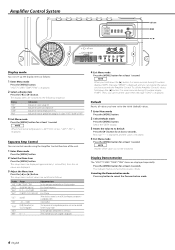
... unit can be initialized. To call the Amplifier Control's values, hold down the [2] button 3 or more seconds during ID number display ("AMP"). Press the [MENU] button for at least 2 seconds. Canceling the Demonstration mode Press any button to ON, low frequency response is set... Control. Select the "DEFA" display. 3 Resets the value to The ID Number you hold down the [3] button 3 or more seconds during ID number display ("AMP"), message "MEMO" is displayed. 4 Exit Menu mode Press the [MENU] button for at least 1 second. The indicator flashes in 3 steps: "FAST", "...
... unit can be initialized. To call the Amplifier Control's values, hold down the [2] button 3 or more seconds during ID number display ("AMP"). Press the [MENU] button for at least 2 seconds. Canceling the Demonstration mode Press any button to ON, low frequency response is set... Control. Select the "DEFA" display. 3 Resets the value to The ID Number you hold down the [3] button 3 or more seconds during ID number display ("AMP"), message "MEMO" is displayed. 4 Exit Menu mode Press the [MENU] button for at least 1 second. The indicator flashes in 3 steps: "FAST", "...
Instruction Manual
Page 7
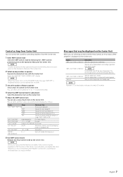
...the amp you use . 6 Exit AMP Control mode Releases the Amp Control mode by 20%. English 7 Control an Amp from the Center Unit. 1 Enter AMP Control mode Select the AMP Control mode by following the instructions given on the Operation Manual of the Center Unit. 2 Select an amp number to the Kenwood's ...dealership. NOTE When the Center Unit is in the Standby mode. Display Range "VOLT"/"CURR"/"TEMP"/"FAN" Adjustment Item The amp state is shorted. "FAN" Indicates the rotation speed of the ...
...the amp you use . 6 Exit AMP Control mode Releases the Amp Control mode by 20%. English 7 Control an Amp from the Center Unit. 1 Enter AMP Control mode Select the AMP Control mode by following the instructions given on the Operation Manual of the Center Unit. 2 Select an amp number to the Kenwood's ...dealership. NOTE When the Center Unit is in the Standby mode. Display Range "VOLT"/"CURR"/"TEMP"/"FAN" Adjustment Item The amp state is shorted. "FAN" Indicates the rotation speed of the ...
Instruction Manual
Page 8
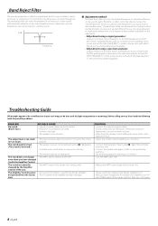
...set the ID number of the Master amplifier to "0". • After you have changed by referring to . • Turn the AMP CONT "ON". • Release the AMP Control mode of resonance or unclear sound with the Amplifier Control. FREQUENCY" control to the position with wrong 9 / · ... sensitivity adjusting control is not pinched by anything. • Set switches properly by the Amplifier Control of the unit. • The AMP Control of a signal generator or a spectrum analyzer with which the vehicle compartment resonates or volume increases (standing waves occur), and set ...
...set the ID number of the Master amplifier to "0". • After you have changed by referring to . • Turn the AMP CONT "ON". • Release the AMP Control mode of resonance or unclear sound with the Amplifier Control. FREQUENCY" control to the position with wrong 9 / · ... sensitivity adjusting control is not pinched by anything. • Set switches properly by the Amplifier Control of the unit. • The AMP Control of a signal generator or a spectrum analyzer with which the vehicle compartment resonates or volume increases (standing waves occur), and set ...

