Instruction Manual
Page 1
KAC-X812D SUBWOOFER POWER AMPLIFIER 7 page 2-9 INSTRUCTION MANUAL AMPLIFICATEUR DE PUISSANCE DU SUBWOOFER 7 page 10-17 MODE D'EMPLOI AMPLIFICADOR DE POTENCIA DEL ALTAVOZ DE SONIDO ENVOLVENTE 7 página 18-25 MANUAL DE INSTRUCCIONES Take the time to the model and serial numbers whenever you obtain the best performance from your Kenwood... dealer for information or service on the warranty card, and in the space provided below. Refer to read through this instruction manual. Model KAC-X812D Serial number US Residence Only Register Online...
KAC-X812D SUBWOOFER POWER AMPLIFIER 7 page 2-9 INSTRUCTION MANUAL AMPLIFICATEUR DE PUISSANCE DU SUBWOOFER 7 page 10-17 MODE D'EMPLOI AMPLIFICADOR DE POTENCIA DEL ALTAVOZ DE SONIDO ENVOLVENTE 7 página 18-25 MANUAL DE INSTRUCCIONES Take the time to the model and serial numbers whenever you obtain the best performance from your Kenwood... dealer for information or service on the warranty card, and in the space provided below. Refer to read through this instruction manual. Model KAC-X812D Serial number US Residence Only Register Online...
Instruction Manual
Page 2
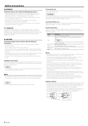
... leave any of operation range. Display "E-01" "E-02" "E-03" "VOLT" display is running, connect a line noise filter (optional) to each amplifier. Informations When the inside the unit. • If the unit starts to emit smoke or strange smells, turn off the power immediately and consult your... the surface of the unit becomes hot and may cause your Kenwood dealer. Do not turn off . The user could lose the authority to operate this equipment may generate or use a new one power amplifier are expressly approved in the instruction manual. FCC WARNING This equipment...
... leave any of operation range. Display "E-01" "E-02" "E-03" "VOLT" display is running, connect a line noise filter (optional) to each amplifier. Informations When the inside the unit. • If the unit starts to emit smoke or strange smells, turn off the power immediately and consult your... the surface of the unit becomes hot and may cause your Kenwood dealer. Do not turn off . The user could lose the authority to operate this equipment may generate or use a new one power amplifier are expressly approved in the instruction manual. FCC WARNING This equipment...
Instruction Manual
Page 3
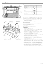
... will become hot during use. English 3 Connect the input and output wires of the battery. 2 CAUTION • Do not install in the unit. 7. Install the amplifier in a place where the cooling fan and ducts of the unit are blocked. Install the terminal cover. 9. Set the unit according to select the proper... the trunk, or somewhere else in the vehicle, check that there is nothing hazardous on top of the unit. • The surface temperature of the amplifier will not obstruct driving. terminal of the units. 4. Connect the negative - Connect the speaker wires. 5.
... will become hot during use. English 3 Connect the input and output wires of the battery. 2 CAUTION • Do not install in the unit. 7. Install the amplifier in a place where the cooling fan and ducts of the unit are blocked. Install the terminal cover. 9. Set the unit according to select the proper... the trunk, or somewhere else in the vehicle, check that there is nothing hazardous on top of the unit. • The surface temperature of the amplifier will not obstruct driving. terminal of the units. 4. Connect the negative - Connect the speaker wires. 5.
Instruction Manual
Page 4
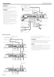
... when you operate any switch. • If the fuse blows, check wires for shorts, then replace the fuse with one of the Master amplifier to fail. • After installation, check that the brake lamps, winkers, and wipers work properly. * Commercially available parts CENTER UNIT (CD...R) 90 1 901 901 901 90 1 901 901 Battery Ground wire* ■ LX-Bus connection CENTER UNIT To Kenwood disc changer/ External optional accessory Power control wire Control cable (option) 30 30 Master amplifier Extension wire* 456 "0" 4 5 6 ID NUMBER S-video cable* 23 23 78 78 RCA cable* Set the ...
... when you operate any switch. • If the fuse blows, check wires for shorts, then replace the fuse with one of the Master amplifier to fail. • After installation, check that the brake lamps, winkers, and wipers work properly. * Commercially available parts CENTER UNIT (CD...R) 90 1 901 901 901 90 1 901 901 Battery Ground wire* ■ LX-Bus connection CENTER UNIT To Kenwood disc changer/ External optional accessory Power control wire Control cable (option) 30 30 Master amplifier Extension wire* 456 "0" 4 5 6 ID NUMBER S-video cable* 23 23 78 78 RCA cable* Set the ...
Instruction Manual
Page 5
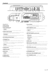
...terminal Controls the unit ON/OFF. NOTE The values you use it to the Center Unit. 9 REMOTE terminals Used to connect to Slave amplifiers. 0 RESET button Resets the microprocessor of the speakers by eliminating unnecessary oscillations which will not become sound. ( ISF FREQUENCY switch Switches .... Be sure to connect it with all the systems. 5 Speaker output terminals As this unit accepts speakers with a minimum impedance of the amplifier. NOTE Amplifier control is possible even while OFF. ^ PHASE switch When this switch is set "180°" (Reverse) the speaker output phase is reversed...
...terminal Controls the unit ON/OFF. NOTE The values you use it to the Center Unit. 9 REMOTE terminals Used to connect to Slave amplifiers. 0 RESET button Resets the microprocessor of the speakers by eliminating unnecessary oscillations which will not become sound. ( ISF FREQUENCY switch Switches .... Be sure to connect it with all the systems. 5 Speaker output terminals As this unit accepts speakers with a minimum impedance of the amplifier. NOTE Amplifier control is possible even while OFF. ^ PHASE switch When this switch is set "180°" (Reverse) the speaker output phase is reversed...
Instruction Manual
Page 6
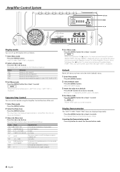
...offset value can be initialized. Indicates the current consumption (A). The setup items are displayed approximately 1 second first, then the set with the Amplifier Control. Volume offset The Fahrenheit or Centigrade temperature unit can not be selected for the Display mode. Select the "DEFA" display. 3...Bass Center Frequency Bass level Bass Q Factor When the bass extend is set to cancel the Demonstration mode. 6 English To call the Amplifier Control's values, hold down the [2] button 3 or more seconds during ID number display ("AMP"). Canceling the Demonstration mode Press any ...
...offset value can be initialized. Indicates the current consumption (A). The setup items are displayed approximately 1 second first, then the set with the Amplifier Control. Volume offset The Fahrenheit or Centigrade temperature unit can not be selected for the Display mode. Select the "DEFA" display. 3...Bass Center Frequency Bass level Bass Q Factor When the bass extend is set to cancel the Demonstration mode. 6 English To call the Amplifier Control's values, hold down the [2] button 3 or more seconds during ID number display ("AMP"). Canceling the Demonstration mode Press any ...
Instruction Manual
Page 7
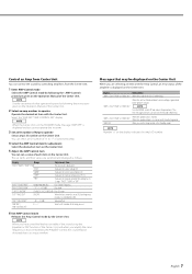
...Display Informations "AMP × E-01"/"AMP × COND E-01" When the inside of the unit is in the Standby mode. "AMP OFF" When you amplify the same frequency as follows. When the unit has failed and direct current voltage is shorted. "AMP × E-03"/"AMP × COND E-03" When the... is set items and their values are selecting an item with the vehicle ground. NOTE Number "×" on the Operation Manual of Amp to the Kenwood's dealership. Control an Amp from Center Unit You can set item with the Center Unit. "VOL"/"VOL OFFSET" -20 - 0 (dB) Volume offset "AMP ...
...Display Informations "AMP × E-01"/"AMP × COND E-01" When the inside of the unit is in the Standby mode. "AMP OFF" When you amplify the same frequency as follows. When the unit has failed and direct current voltage is shorted. "AMP × E-03"/"AMP × COND E-03" When the... is set items and their values are selecting an item with the vehicle ground. NOTE Number "×" on the Operation Manual of Amp to the Kenwood's dealership. Control an Amp from Center Unit You can set item with the Center Unit. "VOL"/"VOL OFFSET" -20 - 0 (dB) Volume offset "AMP ...
Instruction Manual
Page 8
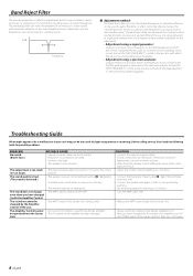
...AMP CONT "ON". • Release the AMP Control mode of the Center Unit. • Always set the ID number of the Master amplifier to "0". • After you have changed by a screw in which all frequencies are connected with a fine frequency measurement capability for possible ...Filter The acoustic properties of vehicle compartment tend to cause oscillation due to resonance or unclearness of resonance or unclear sound with the Amplifier Control. Therefore, its frequency to find the frequencies at which the resonance and standing waves disappear. • Adjustment using a spectrum...
...AMP CONT "ON". • Release the AMP Control mode of the Center Unit. • Always set the ID number of the Master amplifier to "0". • After you have changed by a screw in which all frequencies are connected with a fine frequency measurement capability for possible ...Filter The acoustic properties of vehicle compartment tend to cause oscillation due to resonance or unclearness of resonance or unclear sound with the Amplifier Control. Therefore, its frequency to find the frequencies at which the resonance and standing waves disappear. • Adjustment using a spectrum...
Instruction Manual
Page 9
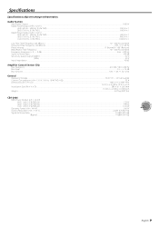
... (variable) Frequency Response (+ 0 , - 3 dB)...5 Hz - 200 Hz Signal to Noise Ratio...100 dB Sensitivity (rated output) (MAX.) ...0.2 V Sensitivity (rated output) (MIN.) ...5.0 V Input Impedance ...10 kΩ Amplifier Control Section (EQ) Bass frequency ...60 / 80 / 100 / 200 Hz Bass level ...-15 - +15 dB Bass Q factor...1.00 / 1.25 / 1.50 / 2.00 General Operating Voltage ...14...
... (variable) Frequency Response (+ 0 , - 3 dB)...5 Hz - 200 Hz Signal to Noise Ratio...100 dB Sensitivity (rated output) (MAX.) ...0.2 V Sensitivity (rated output) (MIN.) ...5.0 V Input Impedance ...10 kΩ Amplifier Control Section (EQ) Bass frequency ...60 / 80 / 100 / 200 Hz Bass level ...-15 - +15 dB Bass Q factor...1.00 / 1.25 / 1.50 / 2.00 General Operating Voltage ...14...


