Instructions
Page 4
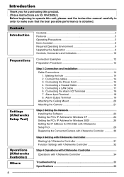
... the Network Installing the Software 23 Setting the PC's IP Address for Windows XP 24 Setting the PC's IP Address for Windows 2000 26 Setting the IP Address for VN-C655U.) Before beginning to operate this product. (These instructions are for VN-C655 with V.Networks Setup Tool 28 Registering the Connected Camera with V.Networks Controller 30 Operations (V.Networks Controller...
... the Network Installing the Software 23 Setting the PC's IP Address for Windows XP 24 Setting the PC's IP Address for Windows 2000 26 Setting the IP Address for VN-C655U.) Before beginning to operate this product. (These instructions are for VN-C655 with V.Networks Setup Tool 28 Registering the Connected Camera with V.Networks Controller 30 Operations (V.Networks Controller...
Instructions
Page 13
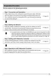
... connect the power cable, LAN cable, alarm and others . ☞ Page 31 Step 4 Operations with V.Networks Setup tool). Step 1 Connection and Installation Firstly, make a hole on to a Ceiling Mount Fix a wire securely for preventing the camera from falling off. ☞ Page 14 Step 2 Setting the Network Install the software [V.Networks Controller], and set the network for VN-
... connect the power cable, LAN cable, alarm and others . ☞ Page 31 Step 4 Operations with V.Networks Setup tool). Step 1 Connection and Installation Firstly, make a hole on to a Ceiling Mount Fix a wire securely for preventing the camera from falling off. ☞ Page 14 Step 2 Setting the Network Install the software [V.Networks Controller], and set the network for VN-

Instructions
Page 18
...UL1015 or equivalent AWG #22 to AWG #18 or equivalent Caution Due to external noise, the camera may not work properly even if the length of the input detection can be selected via software. Preparations (Step 1 Connection and Installation) Cable Connections (continued) 6. Connecting the Alarm I/O ...coating of each cable by loosening the screws on the side to the equipment with a sensor, infrared, door or metallic, or a manual switch. VN-C655 DC18V R Terminal 1 or 2 OUT 18V 0.6mA Sensor Connection Example 1 VCC R Input Requirements • No-voltage relay input or NPN open...
...UL1015 or equivalent AWG #22 to AWG #18 or equivalent Caution Due to external noise, the camera may not work properly even if the length of the input detection can be selected via software. Preparations (Step 1 Connection and Installation) Cable Connections (continued) 6. Connecting the Alarm I/O ...coating of each cable by loosening the screws on the side to the equipment with a sensor, infrared, door or metallic, or a manual switch. VN-C655 DC18V R Terminal 1 or 2 OUT 18V 0.6mA Sensor Connection Example 1 VCC R Input Requirements • No-voltage relay input or NPN open...
Instructions
Page 23
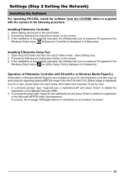
...VN-C10/VN-C11U. (Black image is displayed in mp4sds32.ax succeeded." be shown. 23 Proceed by following procedure. If the installation is successfully executed, the [V.Networks] icon is created in [Programs] of V.Networks Controller with the camera in [V.Networks]. Operation of the Windows [Start] menu. [V.Networks... is created in the [JVC] folder. 2. Installing V.Networks Setup Tool 1. In command prompt, type "regsvr32.exe /u mp4sdmod.dll" and press "Enter" to delete the registration of the Windows [Start] menu. [vn-c655u Setup Tool] is displayed in the following the ...
...VN-C10/VN-C11U. (Black image is displayed in mp4sds32.ax succeeded." be shown. 23 Proceed by following procedure. If the installation is successfully executed, the [V.Networks] icon is created in [Programs] of V.Networks Controller with the camera in [V.Networks]. Operation of the Windows [Start] menu. [V.Networks... is created in the [JVC] folder. 2. Installing V.Networks Setup Tool 1. In command prompt, type "regsvr32.exe /u mp4sdmod.dll" and press "Enter" to delete the registration of the Windows [Start] menu. [vn-c655u Setup Tool] is displayed in the following the ...

