
Instructions
Page 1
which is located on the body. Retain this information for future reference. Model No. VN-C655 Serial No. LWT0202-001A-H DOME TYPE NETWORK CAMERA VN-C655 READ ME FIRST For Customer Use: Enter below the Serial No.
which is located on the body. Retain this information for future reference. Model No. VN-C655 Serial No. LWT0202-001A-H DOME TYPE NETWORK CAMERA VN-C655 READ ME FIRST For Customer Use: Enter below the Serial No.
Instructions
Page 4
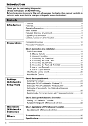
... the IP Address for VN-C655U.) Before beginning to operate this product. (These instructions are for VN-C655 with V.Networks Setup Tool 28 Registering the Connected Camera with V.Networks Controller 30 Operations (V.Networks Controller) Others Step 3 Setting with V.Networks Controller Starting Up V.Networks Controller 31 Function Settings with V.Networks Controller 32 Step 4 Operations with V.Networks Controller Operations with V.Networks Controller 34 Troubleshooting...
... the IP Address for VN-C655U.) Before beginning to operate this product. (These instructions are for VN-C655 with V.Networks Setup Tool 28 Registering the Connected Camera with V.Networks Controller 30 Operations (V.Networks Controller) Others Step 3 Setting with V.Networks Controller Starting Up V.Networks Controller 31 Function Settings with V.Networks Controller 32 Step 4 Operations with V.Networks Controller Operations with V.Networks Controller 34 Troubleshooting...

Instructions
Page 5
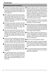
...may become • In a place containing vapor or oil soot, for Ⅵ Day/Night surveillance such cameras to 880 nm). makes it in an upside down position on the network Ⅵ Optical + Electronic zooming without decreasing the frame rate. Operating Precautions Ⅵ To save energy, turn... large difference in 640 x 480 VGA zoom lens has a large aperture ratio of the camera may cause mal- function or a noticeable shortening of 180˚/sec. cold air, for VN-C655. The 25X optical zoom lens and 10X electronic Ⅵ Image Recording Function zoom circuitry ...
...may become • In a place containing vapor or oil soot, for Ⅵ Day/Night surveillance such cameras to 880 nm). makes it in an upside down position on the network Ⅵ Optical + Electronic zooming without decreasing the frame rate. Operating Precautions Ⅵ To save energy, turn... large difference in 640 x 480 VGA zoom lens has a large aperture ratio of the camera may cause mal- function or a noticeable shortening of 180˚/sec. cold air, for VN-C655. The 25X optical zoom lens and 10X electronic Ⅵ Image Recording Function zoom circuitry ...
Instructions
Page 6
...state image pickup devices (CCD) and is a normal phenomenon for 24 camera gain may cause the equipment to VN-C655 deterioration of light cannot be affected by the V.Networks Control- If a transceiver or similar V.Networks Controller operation becoming unstable. of the auto-tracking operation within the white balance... quality of the dome cover and the built-in lens Ⅵ In auto iris mode, the V.Networks Controller may not be viewed prop- As a re- Ⅵ When the camera is used under certain brightness conditions Ⅵ Make sure to erly. To prevent this is enabled, ...
...state image pickup devices (CCD) and is a normal phenomenon for 24 camera gain may cause the equipment to VN-C655 deterioration of light cannot be affected by the V.Networks Control- If a transceiver or similar V.Networks Controller operation becoming unstable. of the auto-tracking operation within the white balance... quality of the dome cover and the built-in lens Ⅵ In auto iris mode, the V.Networks Controller may not be viewed prop- As a re- Ⅵ When the camera is used under certain brightness conditions Ⅵ Make sure to erly. To prevent this is enabled, ...
Instructions
Page 13
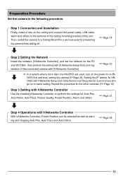
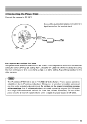
... one and go on to perform the settings for the PC and VN-C655. Step 1 Connection and Installation Firstly, make a hole on the power for a VN- Repeat the procedure for the other cameras. (☞ Page 15) Step 3 Setting with V.Networks Controller With V.Networks Controller, Preset Position can be selected as well as starting and stopping...
... one and go on to perform the settings for the PC and VN-C655. Step 1 Connection and Installation Firstly, make a hole on the power for a VN- Repeat the procedure for the other cameras. (☞ Page 15) Step 3 Setting with V.Networks Controller With V.Networks Controller, Preset Position can be selected as well as starting and stopping...
Instructions
Page 15
...the factory. Or turn off the power once for all network equipment and turn on the power for a VN-C655 first and then setting the camera (☞Page 28, Setting the IP Adress for VN-C655 with multiple VN-C655s In a system where more than one VN-C655 exists on the power for a second one time... under a single LAN environment. Repeat the procedure for some time (at the same time. For a system with V.Networks Setup tool). Note The IP address of VN-C655 is turned on for multiple cameras at one and go on the power for proper access to IP address redundancy if the power is set...
...the factory. Or turn off the power once for all network equipment and turn on the power for a VN-C655 first and then setting the camera (☞Page 28, Setting the IP Adress for VN-C655 with multiple VN-C655s In a system where more than one VN-C655 exists on the power for a second one time... under a single LAN environment. Repeat the procedure for some time (at the same time. For a system with V.Networks Setup tool). Note The IP address of VN-C655 is turned on for multiple cameras at one and go on the power for proper access to IP address redundancy if the power is set...

Instructions
Page 18
...detection can be selected via software. Connecting the Alarm I/O Terminals Connect to the equipment with a sensor, infrared, door or metallic, or a manual switch. VN-C655 DC18V R Terminal 1 or 2 OUT 18V 0.6mA Sensor Connection Example 1 VCC R Input Requirements • No-voltage relay input or NPN open ... mm screwdriver Flat-blade screwdriver • The connector can be released by loosening the screws on the side to external noise, the camera may not work properly even if the length of the cable is for connecting with alarm input terminal using the alarm signal cable. ...
...detection can be selected via software. Connecting the Alarm I/O Terminals Connect to the equipment with a sensor, infrared, door or metallic, or a manual switch. VN-C655 DC18V R Terminal 1 or 2 OUT 18V 0.6mA Sensor Connection Example 1 VCC R Input Requirements • No-voltage relay input or NPN open ... mm screwdriver Flat-blade screwdriver • The connector can be released by loosening the screws on the side to external noise, the camera may not work properly even if the length of the cable is for connecting with alarm input terminal using the alarm signal cable. ...
Instructions
Page 23
... press "Enter" to delete the registration of the Windows [Start] menu. [vn-c655u Setup Tool] is displayed in [V.Networks]. In command prompt, type "regsvr32.exe mp4sds32.ax" and press "Enter" to delete the registration of V.Networks Controller with the camera in [V.Networks]. Open the [JVC] folder and then the "setup" folder inside. If the installation is successfully...
... press "Enter" to delete the registration of the Windows [Start] menu. [vn-c655u Setup Tool] is displayed in [V.Networks]. In command prompt, type "regsvr32.exe mp4sds32.ax" and press "Enter" to delete the registration of V.Networks Controller with the camera in [V.Networks]. Open the [JVC] folder and then the "setup" folder inside. If the installation is successfully...
Instructions
Page 24
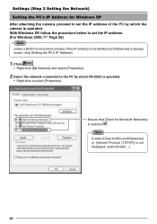
... (TCP/IP)] is not displayed, select [Install ...]. 24 Select the network connected to the PC by which VN-C655 is operated. • Right-click to select [Properties]. Settings (Step 2 Setting the Network) Setting the PC's IP Address for Windows XP After attaching the camera, proceed to set the IP address. (For Windows 2000, ☞...
... (TCP/IP)] is not displayed, select [Install ...]. 24 Select the network connected to the PC by which VN-C655 is operated. • Right-click to select [Properties]. Settings (Step 2 Setting the Network) Setting the PC's IP Address for Windows XP After attaching the camera, proceed to set the IP address. (For Windows 2000, ☞...
Instructions
Page 28
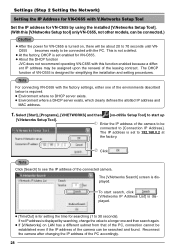
...[V.Networks Setup Tool]. Reconnect the camera after changing the IP address of the camera can be connected.) Caution ● After the power for VN-C655 is set enabled for VN-C655. ● About the DHCP function JVC does not recommend operating VN-C655 with this [V.Networks Setup tool] only VN...which clearly defines the allotted IP address and MAC address. 1. Select [Start], [Programs], [V.NETWORKS] and then [vn-c655u Setup Tool] to [Connection IP Address]. Enter the IP address of the camera to be assigned upon the renewal of the leasing contract. Note Click [Search] to be...
...[V.Networks Setup Tool]. Reconnect the camera after changing the IP address of the camera can be connected.) Caution ● After the power for VN-C655 is set enabled for VN-C655. ● About the DHCP function JVC does not recommend operating VN-C655 with this [V.Networks Setup tool] only VN...which clearly defines the allotted IP address and MAC address. 1. Select [Start], [Programs], [V.NETWORKS] and then [vn-c655u Setup Tool] to [Connection IP Address]. Enter the IP address of the camera to be assigned upon the renewal of the leasing contract. Note Click [Search] to be...
Instructions
Page 29
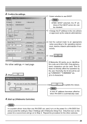
...new IP address becomes effective when VN-C655 is automatically reset. Repeat the procedure for a VN-C655 first and proceed the setting to use DHCP. Click . Click . [V.Networks ID] works as "CAM00001," "CAM00002" etc. (0 to Step 3. Start up [V.Networks Controller]. Click to VN-C655. Note ● With ... a system where more than one alloted, or approved, by the user. Confirm the settings. For other cameras. 29 Select whether to Step 3 Settings with V.Networks Setup Tool. can be checked. Change the IP address to the operating environment. Set the subnet mask to...
...new IP address becomes effective when VN-C655 is automatically reset. Repeat the procedure for a VN-C655 first and proceed the setting to use DHCP. Click . Click . [V.Networks ID] works as "CAM00001," "CAM00002" etc. (0 to Step 3. Start up [V.Networks Controller]. Click to VN-C655. Note ● With ... a system where more than one alloted, or approved, by the user. Confirm the settings. For other cameras. 29 Select whether to Step 3 Settings with V.Networks Setup Tool. can be checked. Change the IP address to the operating environment. Set the subnet mask to...

Instructions
Page 30
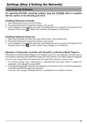
... will be sent at VN-C655. Note ● Images are saved in [IP Address]. Select [Start], [Programs], [V.NETWORKS] and then up to 40 characters) 3 Select the distribution method of the environments described below is required. • Environment where no DHCP server exists. • Environment where a DHCP server, which the camera is registered. When...
... will be sent at VN-C655. Note ● Images are saved in [IP Address]. Select [Start], [Programs], [V.NETWORKS] and then up to 40 characters) 3 Select the distribution method of the environments described below is required. • Environment where no DHCP server exists. • Environment where a DHCP server, which the camera is registered. When...
Instructions
Page 31
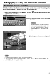
... becomes ready to be controlled with V.Networks Controller) Starting Up V.Networks Controller With the installed Controller, camera images can be monitored. Select [Start], [Programs], [V.NETWORKS] and then up [V.Networks Controller]. [V.Networks Controller] to start 1 In the pull down menu, select the camera to VN-C1, VN-C2, VN-C3, VN-C30 (only for JPEG), VN- can be performed. 1. Note • If a password...
... becomes ready to be controlled with V.Networks Controller) Starting Up V.Networks Controller With the installed Controller, camera images can be monitored. Select [Start], [Programs], [V.NETWORKS] and then up [V.Networks Controller]. [V.Networks Controller] to start 1 In the pull down menu, select the camera to VN-C1, VN-C2, VN-C3, VN-C30 (only for JPEG), VN- can be performed. 1. Note • If a password...
Instructions
Page 36
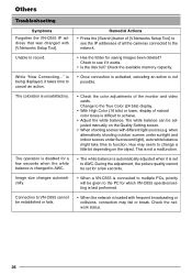
... to the True Color (24 bits) display. • With High Color (16 bits) or lower, display of all the cameras connected to the network. • Has the folder for saving images been deleted? when alternatively shooting outdoor scenes under sunlight and indoor scenes under fluorescent ... to change a little bit depending on the Quality Setting screen. • When shooting scenes with [V.Networks Setup Tool]. is unsatisfactory. Connection to function. Others Troubleshooting Symptoms Forgotten the VN-C655 IP address that was changed to AWC. This is not a malfunction. • The white ...
... to the True Color (24 bits) display. • With High Color (16 bits) or lower, display of all the cameras connected to the network. • Has the folder for saving images been deleted? when alternatively shooting outdoor scenes under sunlight and indoor scenes under fluorescent ... to change a little bit depending on the Quality Setting screen. • When shooting scenes with [V.Networks Setup Tool]. is unsatisfactory. Connection to function. Others Troubleshooting Symptoms Forgotten the VN-C655 IP address that was changed to AWC. This is not a malfunction. • The white ...

Instructions
Page 40
R is a registered trademark owned by Victor Company of Japan, Limited. R is a registered trademark in Thailand LWT0202-001A-H VN-C655 DOME TYPE NETWORK CAMERA and many other countries. © 2004 Victor Company of Japan, Limited. Printed in Japan, the U.S.A., the U.K.
R is a registered trademark owned by Victor Company of Japan, Limited. R is a registered trademark in Thailand LWT0202-001A-H VN-C655 DOME TYPE NETWORK CAMERA and many other countries. © 2004 Victor Company of Japan, Limited. Printed in Japan, the U.S.A., the U.K.


