Instruction Manual
Page 31
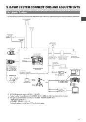
...MV-P615U MV-P618U 3P MIC HOLDER KA-A50U VIDEO LIGHT (ANTON BAUER. PIN (SC46310-001) × 2 2. PROTEC) 1.5" VIEW FINDER VF-P115B VF-P116 DV CAMCORDER ZOOM LENS S14 × 7.3B12U(FUJINON) S17 × 6.6BRM(FUJINON) S20 × 6.4B12U(FUJINON) YH16 × 7K12U(CANON) YH19 × 6.7K12U(... PULL OPEN GY-DV5100 STANDARD PACKAGE TRIPOD BASE FOCUS MANUAL UNIT *1 HZ-FM13 (FUJINON) HZ-FM15 (CANON) ZOOM SERVO UNIT HZ-ZS13B TRIPOD TP-P300 CARRYING CASE DOLLY TP-P205 ANTON BAUER ANTON BAUER BATTERY BATTERY HOLDER (PRO PAC, MAGNUM, (QR JVC DIGI) TRIMPAC, HYTRON) ANTON BAUER BATTERY ...
...MV-P615U MV-P618U 3P MIC HOLDER KA-A50U VIDEO LIGHT (ANTON BAUER. PIN (SC46310-001) × 2 2. PROTEC) 1.5" VIEW FINDER VF-P115B VF-P116 DV CAMCORDER ZOOM LENS S14 × 7.3B12U(FUJINON) S17 × 6.6BRM(FUJINON) S20 × 6.4B12U(FUJINON) YH16 × 7K12U(CANON) YH19 × 6.7K12U(... PULL OPEN GY-DV5100 STANDARD PACKAGE TRIPOD BASE FOCUS MANUAL UNIT *1 HZ-FM13 (FUJINON) HZ-FM15 (CANON) ZOOM SERVO UNIT HZ-ZS13B TRIPOD TP-P300 CARRYING CASE DOLLY TP-P205 ANTON BAUER ANTON BAUER BATTERY BATTERY HOLDER (PRO PAC, MAGNUM, (QR JVC DIGI) TRIMPAC, HYTRON) ANTON BAUER BATTERY ...
Instruction Manual
Page 35
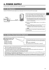
... used up, set to OFF after the DC power is supplied to the VTR section and the camera. * For details, read the instruction manual of the GY-DV5100 to be connected directly to mount the optional battery case. Power is applied. MEMO: Do not remove or connect the DC cable while recording... DV INT DC OUT DC IN TALLY CH-1 CH-2 REAR AUDIO IN Do not use any power source with AC power supply or battery pack. 4-1 AC Operation Use the JVC AA-P250 AC power adapter (max. rated output 12.5 V DC, 3.5 A) as ripples or power sources with a battery pack. POWER SUPPLY The GY-DV5100...
... used up, set to OFF after the DC power is supplied to the VTR section and the camera. * For details, read the instruction manual of the GY-DV5100 to be connected directly to mount the optional battery case. Power is applied. MEMO: Do not remove or connect the DC cable while recording... DV INT DC OUT DC IN TALLY CH-1 CH-2 REAR AUDIO IN Do not use any power source with AC power supply or battery pack. 4-1 AC Operation Use the JVC AA-P250 AC power adapter (max. rated output 12.5 V DC, 3.5 A) as ripples or power sources with a battery pack. POWER SUPPLY The GY-DV5100...
Instruction Manual
Page 38
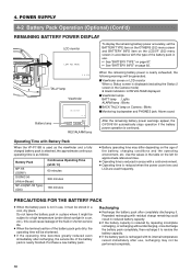
...use , it . OPEN CH-1 AUDIO LEVEL CH-2 LCD BRIGHT FRONT REAR CH-1 CH-2 AUDIO INPUT AUDIO SELECT CH-1 CH-2 AUTO MANUAL DISPLAY PULL OPEN 10.5V TALLY lamp Viewfinder Battery lamp LOW VOLTAGE 10.5V REC BATT ALARM REC/ALARM lamp When the remaining battery power... may differ depending on Camera : Blinks ■ Monitoring loudspeaker and PHONES jack: Alarm sound After the remaining battery power warnings appear, the GY-DV5100 automatically stops operation if the battery power operation is not in a cool, dry place. PRECAUTIONS FOR THE BATTERY PACK ● When the battery...
...use , it . OPEN CH-1 AUDIO LEVEL CH-2 LCD BRIGHT FRONT REAR CH-1 CH-2 AUDIO INPUT AUDIO SELECT CH-1 CH-2 AUTO MANUAL DISPLAY PULL OPEN 10.5V TALLY lamp Viewfinder Battery lamp LOW VOLTAGE 10.5V REC BATT ALARM REC/ALARM lamp When the remaining battery power... may differ depending on Camera : Blinks ■ Monitoring loudspeaker and PHONES jack: Alarm sound After the remaining battery power warnings appear, the GY-DV5100 automatically stops operation if the battery power operation is not in a cool, dry place. PRECAUTIONS FOR THE BATTERY PACK ● When the battery...
Instruction Manual
Page 39
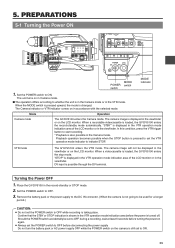
... in the VTR mode. When the MODE switch is pressed upward, the mode is possible through the DV terminal. PREPARATIONS 5-1 Turning the Power ON EDITSEARCH FILTER 1 3200K 2 5600K 1/8 ND .3 5600K .4...CH-2 LCD BRIGHT FRONT REAR CH-1 CH-2 AUDIO INPUT AUDIO SELECT CH-1 CH-2 AUTO MANUAL DISPLAY PULL OPEN MENU AUTO IRIS FULL AUTO BACK L NORMAL SPOT L BLACK LOLUX STRETCH NORMAL...■ The operation differs according to start recording. * Playback is turned off. VTR mode The GY-DV5100 enters the VTR mode. The unit turns on again. ● Always set to indicate STOP. Should...
... in the VTR mode. When the MODE switch is pressed upward, the mode is possible through the DV terminal. PREPARATIONS 5-1 Turning the Power ON EDITSEARCH FILTER 1 3200K 2 5600K 1/8 ND .3 5600K .4...CH-2 LCD BRIGHT FRONT REAR CH-1 CH-2 AUDIO INPUT AUDIO SELECT CH-1 CH-2 AUTO MANUAL DISPLAY PULL OPEN MENU AUTO IRIS FULL AUTO BACK L NORMAL SPOT L BLACK LOLUX STRETCH NORMAL...■ The operation differs according to start recording. * Playback is turned off. VTR mode The GY-DV5100 enters the VTR mode. The unit turns on again. ● Always set to indicate STOP. Should...
Instruction Manual
Page 51
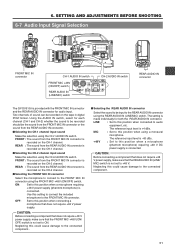
...a microphone (phantom microphone) requiring +48 V DC power supply is connected. PRST FREE REC REGEN PHONES DV INT DC OUT DC IN TALLY CH-1 CH-2 REAR AUDIO IN REAR AUDIO IN connector The GY-DV5100 is recorded on the CH-1 channel. ■ Selecting the CH-2 channel input sound Make the selection ...MONITOR SELECT CH-1 MIX CH-2 REAR AUDIO IN CH-1 CH-2 LINE MIC +48V FRONT REAR CH-1 CH-2 AUDIO IN AUDIO SELECT CH-1 CH-2 AUTO MANUAL COUNTER TC UB TC GENE. The reference input level is made individually for audio input. The reference input level is -60 dBs. +48 V : ...
...a microphone (phantom microphone) requiring +48 V DC power supply is connected. PRST FREE REC REGEN PHONES DV INT DC OUT DC IN TALLY CH-1 CH-2 REAR AUDIO IN REAR AUDIO IN connector The GY-DV5100 is recorded on the CH-1 channel. ■ Selecting the CH-2 channel input sound Make the selection ...MONITOR SELECT CH-1 MIX CH-2 REAR AUDIO IN CH-1 CH-2 LINE MIC +48V FRONT REAR CH-1 CH-2 AUDIO IN AUDIO SELECT CH-1 CH-2 AUTO MANUAL COUNTER TC UB TC GENE. The reference input level is made individually for audio input. The reference input level is -60 dBs. +48 V : ...
Instruction Manual
Page 54
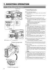
... MODE VTR CAM POWER VTR ON OFF OPEN CH-1 AUDIO LEVEL CH-2 LCD BRIGHT FRONT REAR CH-1 CH-2 AUDIO IN AUDIO SELECT CH-1 CH-2 AUTO MANUAL DISPLAY PULL OPEN POWER VTR ON OFF 1. 7. 8. 9. MODE VTR CAM 2. 6. Focusing ring EDITSEARCH FILTER 1 3200K 2 5600K 1/8 ND .3 5600K ...the focusing ring. 7. MEMO: ● Use a standard DV videocassette or a MiniDV videocassette. (When a DVCAM cassette is recording. TALLY lamp 1. Set the POWER switch to ON. ● Power is on the DVCAM cassette. The GY-DV5100 is in the viewfinder lights green. Adjust the camera section ...
... MODE VTR CAM POWER VTR ON OFF OPEN CH-1 AUDIO LEVEL CH-2 LCD BRIGHT FRONT REAR CH-1 CH-2 AUDIO IN AUDIO SELECT CH-1 CH-2 AUTO MANUAL DISPLAY PULL OPEN POWER VTR ON OFF 1. 7. 8. 9. MODE VTR CAM 2. 6. Focusing ring EDITSEARCH FILTER 1 3200K 2 5600K 1/8 ND .3 5600K ...the focusing ring. 7. MEMO: ● Use a standard DV videocassette or a MiniDV videocassette. (When a DVCAM cassette is recording. TALLY lamp 1. Set the POWER switch to ON. ● Power is on the DVCAM cassette. The GY-DV5100 is in the viewfinder lights green. Adjust the camera section ...

Instruction Manual
Page 55
... sound of the tape, a blank space appears as required. ■ When it is pressed, the viewfinder REC indicator lamp may blink and the GY-DV5100 may also occur.) 7.8. To restart recording: Press the VTR trigger button on page 86. ● If the VTR trigger button is pressed very ...repeatedly, or the POWER switch is moved immediately after the videocassette is inserted, the mode becomes the QUICK REC START mode that the iris is manually moved abruptly during shooting. 55 To remedy this mode continues for a long period, detach the battery pack. SHOOTING OPERATION REC BATT ALARM 7.8 ...
... sound of the tape, a blank space appears as required. ■ When it is pressed, the viewfinder REC indicator lamp may blink and the GY-DV5100 may also occur.) 7.8. To restart recording: Press the VTR trigger button on page 86. ● If the VTR trigger button is pressed very ...repeatedly, or the POWER switch is moved immediately after the videocassette is inserted, the mode becomes the QUICK REC START mode that the iris is manually moved abruptly during shooting. 55 To remedy this mode continues for a long period, detach the battery pack. SHOOTING OPERATION REC BATT ALARM 7.8 ...
Instruction Manual
Page 61
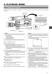
.... ● The VTR mode is selected on the menu screen: Display of date and time : TIME/DATE menu screen Display of videocassettes: • DV videocassette • MiniDV videocassette • DVCAM videocassette ● Tapes recorded in the viewfinder. (Status screen) TC00:00:00:00 20min PLAY 12.2V ... REAR CH-1 CH-2 AUDIO IN AUDIO SELECT CH-1 CH-2 AUTO MANUAL DISPLAY PULL OPEN BLANK SEARCH REW STOP FF PLAY STILL MODE VTR CAM Still button PLAY button STOP button POWER switch MODE switch MEMO: ● The GY-DV5100 can play back the following three types of time code : LCD...
.... ● The VTR mode is selected on the menu screen: Display of date and time : TIME/DATE menu screen Display of videocassettes: • DV videocassette • MiniDV videocassette • DVCAM videocassette ● Tapes recorded in the viewfinder. (Status screen) TC00:00:00:00 20min PLAY 12.2V ... REAR CH-1 CH-2 AUDIO IN AUDIO SELECT CH-1 CH-2 AUTO MANUAL DISPLAY PULL OPEN BLANK SEARCH REW STOP FF PLAY STILL MODE VTR CAM Still button PLAY button STOP button POWER switch MODE switch MEMO: ● The GY-DV5100 can play back the following three types of time code : LCD...

Instruction Manual
Page 64
... is capable of recording up to display the TOP MENU screen. 2. TC/UB/CLOCK.. Press the STATUS button for playback of DV input.) When the GY-DV5100 is used for 1 second or longer to 4 channels when the 12-bit, 32 kHz sampling frequency is confirmed. 6. MIX : To reproduce the sound recorded...VTR CAM POWER VTR ON OFF OPEN CH-1 AUDIO LEVEL CH-2 LCD BRIGHT FRONT REAR CH-1 CH-2 AUDIO IN AUDIO SELECT CH-1 CH-2 AUTO MANUAL DISPLAY PULL OPEN TOP MENU screen --- FILE MANAGE.. TEST TONE ON AUDIO MODE 32K A.OUT AT SEARCH ON CH1 FRONT VR ENABLE WIND CUT ...
... is capable of recording up to display the TOP MENU screen. 2. TC/UB/CLOCK.. Press the STATUS button for playback of DV input.) When the GY-DV5100 is used for 1 second or longer to 4 channels when the 12-bit, 32 kHz sampling frequency is confirmed. 6. MIX : To reproduce the sound recorded...VTR CAM POWER VTR ON OFF OPEN CH-1 AUDIO LEVEL CH-2 LCD BRIGHT FRONT REAR CH-1 CH-2 AUDIO IN AUDIO SELECT CH-1 CH-2 AUTO MANUAL DISPLAY PULL OPEN TOP MENU screen --- FILE MANAGE.. TEST TONE ON AUDIO MODE 32K A.OUT AT SEARCH ON CH1 FRONT VR ENABLE WIND CUT ...
Instruction Manual
Page 65
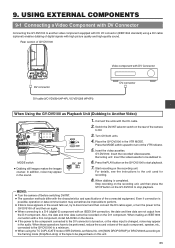
... GY-DV5100 PHONES DV INT DC OUT DC IN TALLY CH-1 CH-2 REAR AUDIO IN DV connector DV cable (VC-VDV204 (4P-4P), VC-VDV206 (4P-6P)) Video component with DV Connector DV connector When Using the GY-DV5100 as Playback Unit (Dubbing to . Place the GY-DV5100 in the sound. Start recording on the GY-DV5100 ...LCD BRIGHT FRONT REAR CH-1 CH-2 AUDIO IN AUDIO SELECT CH-1 CH-2 AUTO MANUAL DISPLAY PULL OPEN MODE VTR CAM 3. 9. Insert the videocassettes. For details, see the instructions to the DV connector is turned on, or the video input is completed. When making an ...
... GY-DV5100 PHONES DV INT DC OUT DC IN TALLY CH-1 CH-2 REAR AUDIO IN DV connector DV cable (VC-VDV204 (4P-4P), VC-VDV206 (4P-6P)) Video component with DV Connector DV connector When Using the GY-DV5100 as Playback Unit (Dubbing to . Place the GY-DV5100 in the sound. Start recording on the GY-DV5100 ...LCD BRIGHT FRONT REAR CH-1 CH-2 AUDIO IN AUDIO SELECT CH-1 CH-2 AUTO MANUAL DISPLAY PULL OPEN MODE VTR CAM 3. 9. Insert the videocassettes. For details, see the instructions to the DV connector is turned on, or the video input is completed. When making an ...
Instruction Manual
Page 66
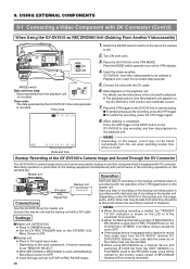
...02/03 01:23:45 Date and time MEMO: Depending on the rear of BR-DV600A or BR-DV3000 is equipped with DV Connector (Cont'd) When Using the GY-DV5100 as the master unit. Playback unit: Insert the recorded videocassette. 5. Master unit Operation EDITSEARCH FILTER 1 3200K 2 5600K 1/8 ...CH-1 AUDIO LEVEL CH-2 LCD BRIGHT FRONT REAR CH-1 CH-2 AUDIO IN AUDIO SELECT CH-1 CH-2 AUTO MANUAL DISPLAY PULL OPEN DV cable Signal flow Backup unit Connections Use the GY-DV5100 as RECORDING Unit (Dubbing From Another Videocassette) EDITSEARCH FILTER 1 3200K 2 5600K 1/8 ND .3 5600K .4 5600K ...
...02/03 01:23:45 Date and time MEMO: Depending on the rear of BR-DV600A or BR-DV3000 is equipped with DV Connector (Cont'd) When Using the GY-DV5100 as the master unit. Playback unit: Insert the recorded videocassette. 5. Master unit Operation EDITSEARCH FILTER 1 3200K 2 5600K 1/8 ...CH-1 AUDIO LEVEL CH-2 LCD BRIGHT FRONT REAR CH-1 CH-2 AUDIO IN AUDIO SELECT CH-1 CH-2 AUTO MANUAL DISPLAY PULL OPEN DV cable Signal flow Backup unit Connections Use the GY-DV5100 as RECORDING Unit (Dubbing From Another Videocassette) EDITSEARCH FILTER 1 3200K 2 5600K 1/8 ND .3 5600K .4 5600K ...
Instruction Manual
Page 67
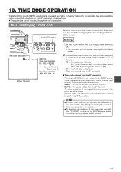
...connectors. 10-1 Displaying Time Code OPEN CH-1 AUDIO LEVEL CH-2 LCD BRIGHT FRONT REAR CH-1 CH-2 AUDIO IN AUDIO SELECT CH-1 CH-2 AUTO MANUAL DISPLAY PULL OPEN COUNTER switch LCD BRIGHT DISPLAY CH-1 AUDIO LEVEL CH-2 FRONT MIC +48V ON OFF MONITOR SELECT CH-1 MIX CH-2 REAR AUDIO IN...restored by performing VTR operation.) MEMO: ● The time code and user's bit input from the DV terminal. 67 Set the TC/UB item on the Status screen. TIME CODE OPERATION The GY-DV5100 records SMPTE-standard time codes and user's bits. The data generated by the camera's time code ...
...connectors. 10-1 Displaying Time Code OPEN CH-1 AUDIO LEVEL CH-2 LCD BRIGHT FRONT REAR CH-1 CH-2 AUDIO IN AUDIO SELECT CH-1 CH-2 AUTO MANUAL DISPLAY PULL OPEN COUNTER switch LCD BRIGHT DISPLAY CH-1 AUDIO LEVEL CH-2 FRONT MIC +48V ON OFF MONITOR SELECT CH-1 MIX CH-2 REAR AUDIO IN...restored by performing VTR operation.) MEMO: ● The time code and user's bit input from the DV terminal. 67 Set the TC/UB item on the Status screen. TIME CODE OPERATION The GY-DV5100 records SMPTE-standard time codes and user's bits. The data generated by the camera's time code ...
Instruction Manual
Page 70
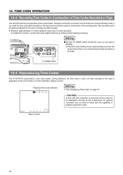
...-1 CH-2 LINE MIC +48V FRONT REAR CH-1 CH-2 AUDIO IN AUDIO SELECT CH-1 CH-2 AUTO MANUAL COUNTER TC UB TC GENE. CAUTION: A time code with a duration of the existing data. TIME ... on tape. ● However, approximately ±1-frame variations may not be displayed correctly by DV components for general consumer use, as follows before starting recording. Therefore, when the unit enters ... switch inside the cover on the side to the user's bit data recorded on Tape The GY-DV5100 also incorporates a time code reader. During playback, the time code or user's bit data recorded...
...-1 CH-2 LINE MIC +48V FRONT REAR CH-1 CH-2 AUDIO IN AUDIO SELECT CH-1 CH-2 AUTO MANUAL COUNTER TC UB TC GENE. CAUTION: A time code with a duration of the existing data. TIME ... on tape. ● However, approximately ±1-frame variations may not be displayed correctly by DV components for general consumer use, as follows before starting recording. Therefore, when the unit enters ... switch inside the cover on the side to the user's bit data recorded on Tape The GY-DV5100 also incorporates a time code reader. During playback, the time code or user's bit data recorded...

Instruction Manual
Page 72
... steps 5. Return to be made. 6. Rotate the SHUTTER dial to 7. 11. CAMERA PROCESS.. OTHERS.. CAMERA OPERATION --- item on page 73. 8. Set the mode of the GY-DV5100 with the EXIT item, and then press the SHUTTER dial. 72 above . ■ To save the set , and then press the SHUTTER dial. ● The... MODE VTR CAM POWER VTR ON OFF OPEN CH-1 AUDIO LEVEL CH-2 LCD BRIGHT FRONT REAR CH-1 CH-2 AUDIO IN AUDIO SELECT CH-1 CH-2 AUTO MANUAL DISPLAY PULL OPEN SHUTTER dial STATUS button SHUTTER STA MENU Cursor MENU screen --- TC/UB/CLOCK.. and 6.
... steps 5. Return to be made. 6. Rotate the SHUTTER dial to 7. 11. CAMERA PROCESS.. OTHERS.. CAMERA OPERATION --- item on page 73. 8. Set the mode of the GY-DV5100 with the EXIT item, and then press the SHUTTER dial. 72 above . ■ To save the set , and then press the SHUTTER dial. ● The... MODE VTR CAM POWER VTR ON OFF OPEN CH-1 AUDIO LEVEL CH-2 LCD BRIGHT FRONT REAR CH-1 CH-2 AUDIO IN AUDIO SELECT CH-1 CH-2 AUTO MANUAL DISPLAY PULL OPEN SHUTTER dial STATUS button SHUTTER STA MENU Cursor MENU screen --- TC/UB/CLOCK.. and 6.

Instruction Manual
Page 96
...9679; Improper operation caution area (Display area: A) Indication Condition Remedy INVALID TAPE! MEMO: The GY-DV5100 is used. videocassette for PC or DVCPRO videocassette Use a standard DV videocassette or MiniDV use . NO DV SIGNAL DV signal is loaded. NO TAPE No videocassette is not input. A copy-guarded tape cannot be ... POWER VTR ON OFF OPEN CH-1 AUDIO LEVEL CH-2 LCD BRIGHT FRONT REAR CH-1 CH-2 AUDIO IN AUDIO SELECT CH-1 CH-2 AUTO MANUAL DISPLAY PULL OPEN TALLY lamp LOW VOLTAGE FAS dB NO TAPE FAW I B 12.2V 01/02/03 01:23:45 A: Improper operation ...
...9679; Improper operation caution area (Display area: A) Indication Condition Remedy INVALID TAPE! MEMO: The GY-DV5100 is used. videocassette for PC or DVCPRO videocassette Use a standard DV videocassette or MiniDV use . NO DV SIGNAL DV signal is loaded. NO TAPE No videocassette is not input. A copy-guarded tape cannot be ... POWER VTR ON OFF OPEN CH-1 AUDIO LEVEL CH-2 LCD BRIGHT FRONT REAR CH-1 CH-2 AUDIO IN AUDIO SELECT CH-1 CH-2 AUTO MANUAL DISPLAY PULL OPEN TALLY lamp LOW VOLTAGE FAS dB NO TAPE FAW I B 12.2V 01/02/03 01:23:45 A: Improper operation ...
Instruction Manual
Page 100
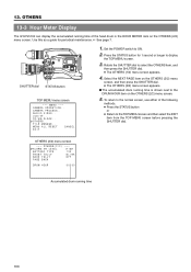
... screen and then select the EXIT item from the TOP MENU screen before pressing the SHUTTER dial. CAMERA PROCESS.. OTHERS 13-3 Hour Meter Display The GY-DV5100 can display the accumulated running time of the following methods. ● Press the STATUS button or ● Return to display the TOP MENU screen. 3. LCD... MODE VTR CAM POWER VTR ON OFF OPEN CH-1 AUDIO LEVEL CH-2 LCD BRIGHT FRONT REAR CH-1 CH-2 AUDIO IN AUDIO SELECT CH-1 CH-2 AUTO MANUAL DISPLAY PULL OPEN SHUTTER dial STATUS button TOP MENU menu screen --- OTHERS (2/2) menu screen ---
... screen and then select the EXIT item from the TOP MENU screen before pressing the SHUTTER dial. CAMERA PROCESS.. OTHERS 13-3 Hour Meter Display The GY-DV5100 can display the accumulated running time of the following methods. ● Press the STATUS button or ● Return to display the TOP MENU screen. 3. LCD... MODE VTR CAM POWER VTR ON OFF OPEN CH-1 AUDIO LEVEL CH-2 LCD BRIGHT FRONT REAR CH-1 CH-2 AUDIO IN AUDIO SELECT CH-1 CH-2 AUTO MANUAL DISPLAY PULL OPEN SHUTTER dial STATUS button TOP MENU menu screen --- OTHERS (2/2) menu screen ---

