Instruction Manual
Page 4
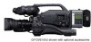
... sure to displaying the camera image and the playback image, the LCD monitor shows the status screens, menu screens for settings, and alarm indications. ● Built-in monitor speaker for high-quality picture 1/2" 3-CCD with DV connector, such as computer monitor screens. This is not possible. Enables transfer of digital data to tracking errors. ● This unit records and plays back in the DVCAM format is ideal for purchasing the DV Camcorder GY-DV5100...
... sure to displaying the camera image and the playback image, the LCD monitor shows the status screens, menu screens for settings, and alarm indications. ● Built-in monitor speaker for high-quality picture 1/2" 3-CCD with DV connector, such as computer monitor screens. This is not possible. Enables transfer of digital data to tracking errors. ● This unit records and plays back in the DVCAM format is ideal for purchasing the DV Camcorder GY-DV5100...

Instruction Manual
Page 5
... Actions 96 13-2 Troubleshooting 99 13-3 Hour Meter Display 100 13-4 Specifications 101 5 PREPARATIONS 5-1 Turning the Power ON 39 5-2 Cassette Loading and Unloading 40 5-3 Viewing the LCD Monitor 42 5-4 Setting, Displaying and Recording the Date and Time 43 5-5 Charging the Built-in Continuation of Time Codes Recorded on Tape 70 10-4 Reproducing Time Codes 70 11. TIME CODE OPERATION 10-1 Displaying Time Code 67 10-2 Presetting and Recording of Head Cleaning Tape 7 1-4 Videocassette to be Used 8 1-5 Battery Pack to Use Skin Detail 94...
... Actions 96 13-2 Troubleshooting 99 13-3 Hour Meter Display 100 13-4 Specifications 101 5 PREPARATIONS 5-1 Turning the Power ON 39 5-2 Cassette Loading and Unloading 40 5-3 Viewing the LCD Monitor 42 5-4 Setting, Displaying and Recording the Date and Time 43 5-5 Charging the Built-in Continuation of Time Codes Recorded on Tape 70 10-4 Reproducing Time Codes 70 11. TIME CODE OPERATION 10-1 Displaying Time Code 67 10-2 Presetting and Recording of Head Cleaning Tape 7 1-4 Videocassette to be Used 8 1-5 Battery Pack to Use Skin Detail 94...
Instruction Manual
Page 6
... is displayed and correct playback will not take place. If the power voltage is not a camera malfunction. ● Noise may not turn OFF the setup level, set the SET UP item on the CCD elements could be serious as small white spots may be generated. ● Strong electromagnetic waves or magnetism Noise may appear in the picture or audio and/or the colors may...
... is displayed and correct playback will not take place. If the power voltage is not a camera malfunction. ● Noise may not turn OFF the setup level, set the SET UP item on the CCD elements could be serious as small white spots may be generated. ● Strong electromagnetic waves or magnetism Noise may appear in the picture or audio and/or the colors may...
Instruction Manual
Page 7
... video and audio quality at the most for use of failure. INTRODUCTION 1-2 Routine and Periodical Maintenance The GY-DV5100 incorporates precision mechanical parts, which penetrates the inside of the VCR section during playback, edit search, and recording check using the cleaning tape, please follow the instructions of this sheet. Block Noise ● Please use head cleaning tapes other than four times at high levels. For details, see "HOUR METER DISPLAY...
... video and audio quality at the most for use of failure. INTRODUCTION 1-2 Routine and Periodical Maintenance The GY-DV5100 incorporates precision mechanical parts, which penetrates the inside of the VCR section during playback, edit search, and recording check using the cleaning tape, please follow the instructions of this sheet. Block Noise ● Please use head cleaning tapes other than four times at high levels. For details, see "HOUR METER DISPLAY...
Instruction Manual
Page 10
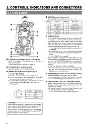
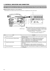
... AREA AUTO WHITE ACCU FOCUS VTR AUDIO LEVEL CH-1 5 i u 1 Viewfinder mount base, sliding securing ring Mount the viewfinder on the base and secure it using a microphone other than a phantom microphone, first set to "FRONT". ☞ See page 16. 1 3 2 Pin No. 1 2 3 Function GND HOT COLD 4 [LENS] Lens control connector Connect 12-pin lens control cable from the viewfinder here. 3 [FRONT MIC IN] Front microphone input connector (XLR 3-pin) Balanced 3-pin connector for manual adjustment...
... AREA AUTO WHITE ACCU FOCUS VTR AUDIO LEVEL CH-1 5 i u 1 Viewfinder mount base, sliding securing ring Mount the viewfinder on the base and secure it using a microphone other than a phantom microphone, first set to "FRONT". ☞ See page 16. 1 3 2 Pin No. 1 2 3 Function GND HOT COLD 4 [LENS] Lens control connector Connect 12-pin lens control cable from the viewfinder here. 3 [FRONT MIC IN] Front microphone input connector (XLR 3-pin) Balanced 3-pin connector for manual adjustment...
Instruction Manual
Page 16
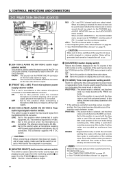
... "AUDIO/VIDEO Menu Screen" on page 79. CH-2 : The CH-2 channel audio is connected. CONTROLS, INDICATORS AND CONNECTORS 2-2 Right Side Section (Cont'd) 1 3200K 2 5600K 1/8 ND .3 5600K .4 5600K 1/64 ND SHUTTER STATUS MENU AUTO IRIS FULL AUTO BACK L NORMAL SPOT L BLACK LOLUX STRETCH NORMAL COMPRESS MODE VTR CAM CH-1 AUDIO LEVEL CH-2 LCD BRIGHT FRONT REAR CH-1 CH-2 AUDIO INPUT AUDIO SELECT CH-1 CH-2 AUTO MANUAL DISPLAY PULL OPEN POWER VTR VieON w with the time code or user's bits set...
... "AUDIO/VIDEO Menu Screen" on page 79. CH-2 : The CH-2 channel audio is connected. CONTROLS, INDICATORS AND CONNECTORS 2-2 Right Side Section (Cont'd) 1 3200K 2 5600K 1/8 ND .3 5600K .4 5600K 1/64 ND SHUTTER STATUS MENU AUTO IRIS FULL AUTO BACK L NORMAL SPOT L BLACK LOLUX STRETCH NORMAL COMPRESS MODE VTR CAM CH-1 AUDIO LEVEL CH-2 LCD BRIGHT FRONT REAR CH-1 CH-2 AUDIO INPUT AUDIO SELECT CH-1 CH-2 AUTO MANUAL DISPLAY PULL OPEN POWER VTR VieON w with the time code or user's bits set...

Instruction Manual
Page 19
... alarm sound is output. When a cable is connected here, the power supply from this connector can be output is selected with the AUDIO SELECT item on the AUDIO/VIDEO menu screen and MONITOR SELECT switch C on page 16 in accordance with the REM FF/REW MODE item on the channel set to "REAR". DV: Connect a digital video component to the DV connector INT: Connect a DV Disk Recorder to the camera * Turn the camera off before using a stereotype...
... alarm sound is output. When a cable is connected here, the power supply from this connector can be output is selected with the AUDIO SELECT item on the AUDIO/VIDEO menu screen and MONITOR SELECT switch C on page 16 in accordance with the REM FF/REW MODE item on the channel set to "REAR". DV: Connect a digital video component to the DV connector INT: Connect a DV Disk Recorder to the camera * Turn the camera off before using a stereotype...
Instruction Manual
Page 24
... ▼ : Iris set on the TIME/DATE MENU screen. ☞ page 45 "Displaying the Time and Date on the Screen" 24 Audio sampling frequency and audio level adjustment method (Example) 32K (CH1 Å CH2 ˜ ) Å (Auto) ˜ (Manual) ● Status 3 This screen only displays date and time, event display and warning indications. * Whether or not date and time should be switched ON/OFF with the FILTER item on the LCD/VF (1/2) menu screen. OPEN, F2, F2...
... ▼ : Iris set on the TIME/DATE MENU screen. ☞ page 45 "Displaying the Time and Date on the Screen" 24 Audio sampling frequency and audio level adjustment method (Example) 32K (CH1 Å CH2 ˜ ) Å (Auto) ˜ (Manual) ● Status 3 This screen only displays date and time, event display and warning indications. * Whether or not date and time should be switched ON/OFF with the FILTER item on the LCD/VF (1/2) menu screen. OPEN, F2, F2...
Instruction Manual
Page 25
... display method with the TAPE REMAIN item on the TIME/DATE menu screen. Whether or not to show the time code or the user's bits is selected with the AUDIO item on the LCD/ VF (2/2) menu screen. 8 VTR mode indication Indicates the VTR operation status. Whether or not the date and time should be used only as a guide. * When the unit is used for the recording is in reverse direction (SLOW-1: About ×-0.1 speed, SLOW...
... display method with the TAPE REMAIN item on the TIME/DATE menu screen. Whether or not to show the time code or the user's bits is selected with the AUDIO item on the LCD/ VF (2/2) menu screen. 8 VTR mode indication Indicates the VTR operation status. Whether or not the date and time should be used only as a guide. * When the unit is used for the recording is in reverse direction (SLOW-1: About ×-0.1 speed, SLOW...
Instruction Manual
Page 26
... mode, the displayed contents change every time the DISPLAY button is set status of a tape recorded in drop frame mode. FREE : TC GENE switch is set to the video signal. Displays time code. NDF : During playback of the TC GENE switch on the LCD monitor. 1 EDITSEARCH FILTER 1 3200K 2 5600K 1/8 ND .3 5600K .4 5600K 1/64 ND SHUTTER STATUS MONITOR MENU AUTO IRIS FULL AUTO BACK L NORMAL SPOT L BLACK LOLUX STRETCH NORMAL COMPRESS MODE VTR CAM POWER VTR ON OFF OPEN CH-1 AUDIO LEVEL...
... mode, the displayed contents change every time the DISPLAY button is set status of a tape recorded in drop frame mode. FREE : TC GENE switch is set to the video signal. Displays time code. NDF : During playback of the TC GENE switch on the LCD monitor. 1 EDITSEARCH FILTER 1 3200K 2 5600K 1/8 ND .3 5600K .4 5600K 1/64 ND SHUTTER STATUS MONITOR MENU AUTO IRIS FULL AUTO BACK L NORMAL SPOT L BLACK LOLUX STRETCH NORMAL COMPRESS MODE VTR CAM POWER VTR ON OFF OPEN CH-1 AUDIO LEVEL...
Instruction Manual
Page 31
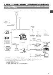
... L BLACK LOLUX STRETCH NORMAL COMPRESS MODE VTR CAM POWER VTR ON OFF OPEN CH-1 AUDIO LEVEL CH-2 LCD BRIGHT FRONT REAR CH-1 CH-2 AUDIO IN AUDIO SELECT CH-1 CH-2 AUTO MANUAL DISPLAY PULL OPEN GY-DV5100 STANDARD PACKAGE TRIPOD BASE FOCUS MANUAL UNIT *1 HZ-FM13 (FUJINON) HZ-FM15 (CANON) ZOOM SERVO UNIT HZ-ZS13B TRIPOD TP-P300 CARRYING CASE DOLLY TP-P205 ANTON BAUER ANTON BAUER BATTERY BATTERY HOLDER (PRO PAC...
... L BLACK LOLUX STRETCH NORMAL COMPRESS MODE VTR CAM POWER VTR ON OFF OPEN CH-1 AUDIO LEVEL CH-2 LCD BRIGHT FRONT REAR CH-1 CH-2 AUDIO IN AUDIO SELECT CH-1 CH-2 AUTO MANUAL DISPLAY PULL OPEN GY-DV5100 STANDARD PACKAGE TRIPOD BASE FOCUS MANUAL UNIT *1 HZ-FM13 (FUJINON) HZ-FM15 (CANON) ZOOM SERVO UNIT HZ-ZS13B TRIPOD TP-P300 CARRYING CASE DOLLY TP-P205 ANTON BAUER ANTON BAUER BATTERY BATTERY HOLDER (PRO PAC...
Instruction Manual
Page 43
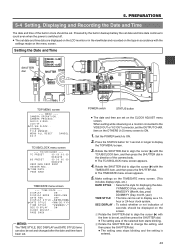
... COMPRESS MODE VTR CAM POWER VTR ON OFF OPEN CH-1 AUDIO LEVEL CH-2 LCD BRIGHT FRONT REAR CH-1 CH-2 AUDIO INPUT AUDIO SELECT CH-1 CH-2 AUTO MANUAL DISPLAY PULL OPEN TOP MENU screen --- TC/UB/CLOCK.. When setting while observing on a monitor connected to align the cursor ( ) with the settings made on the CLOCK ADJUST menu screen. OTHERS.. PREPARATIONS 5-4 Setting, Displaying and Recording the Date and Time The date and time of the selected item starts blinking. 2 Rotate the SHUTTER dial...
... COMPRESS MODE VTR CAM POWER VTR ON OFF OPEN CH-1 AUDIO LEVEL CH-2 LCD BRIGHT FRONT REAR CH-1 CH-2 AUDIO INPUT AUDIO SELECT CH-1 CH-2 AUTO MANUAL DISPLAY PULL OPEN TOP MENU screen --- TC/UB/CLOCK.. When setting while observing on a monitor connected to align the cursor ( ) with the settings made on the CLOCK ADJUST menu screen. OTHERS.. PREPARATIONS 5-4 Setting, Displaying and Recording the Date and Time The date and time of the selected item starts blinking. 2 Rotate the SHUTTER dial...
Instruction Manual
Page 45
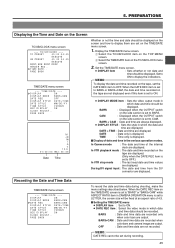
.... ● DATE REC item : Select the video mode in CAMERA OPERATION menu is displayed. DATE : Date only is set to "BARS" or "BARS+CAM" while ASPECT RATIO item in which date and time should be displayed on the TIME/DATE screen is set to LETTER, the screen size will be set to ON. ● DISPLAY MODE item : Sets the video output mode in the various operation modes. In Camera mode : The date and time of the internal clock are not recorded. Recording the Date and Time Data TIME/DATE menu screen --- When the DATE REC item...
.... ● DATE REC item : Select the video mode in CAMERA OPERATION menu is displayed. DATE : Date only is set to "BARS" or "BARS+CAM" while ASPECT RATIO item in which date and time should be displayed on the TIME/DATE screen is set to LETTER, the screen size will be set to ON. ● DISPLAY MODE item : Sets the video output mode in the various operation modes. In Camera mode : The date and time of the internal clock are not recorded. Recording the Date and Time Data TIME/DATE menu screen --- When the DATE REC item...
Instruction Manual
Page 59
... and the Record- HEADER REC --- Set the MODE switch to the beginning, and HEADER REC operation starts from the beginning of the selected item starts blinking. 2 Changing the setting value. MEMO: ● The HEADER REC menu screen cannot be set the HEADER REC menu screen HEADER REC menu screen --- Setting the HEADER REC menu screen. 1 Select the menu item. Display the HEADER REC menu screen. 7. SHOOTING OPERATION ■ How to be opened during loading of the cassette tape. ● The date and time recorded in the color bar...
... and the Record- HEADER REC --- Set the MODE switch to the beginning, and HEADER REC operation starts from the beginning of the selected item starts blinking. 2 Changing the setting value. MEMO: ● The HEADER REC menu screen cannot be set the HEADER REC menu screen HEADER REC menu screen --- Setting the HEADER REC menu screen. 1 Select the menu item. Display the HEADER REC menu screen. 7. SHOOTING OPERATION ■ How to be opened during loading of the cassette tape. ● The date and time recorded in the color bar...
Instruction Manual
Page 61
... ND SHUTTER STATUS MONITOR MENU AUTO IRIS FULL AUTO BACK L NORMAL SPOT L BLACK LOLUX STRETCH NORMAL COMPRESS MODE VTR CAM POWER VTR ON OFF OPEN CH-1 AUDIO LEVEL CH-2 LCD BRIGHT FRONT REAR CH-1 CH-2 AUDIO IN AUDIO SELECT CH-1 CH-2 AUTO MANUAL DISPLAY PULL OPEN BLANK SEARCH REW STOP FF PLAY STILL MODE VTR CAM Still button PLAY button STOP button POWER switch MODE switch MEMO: ● The GY-DV5100 can be shown on another unit, digital noise may appear during playback. ●...
... ND SHUTTER STATUS MONITOR MENU AUTO IRIS FULL AUTO BACK L NORMAL SPOT L BLACK LOLUX STRETCH NORMAL COMPRESS MODE VTR CAM POWER VTR ON OFF OPEN CH-1 AUDIO LEVEL CH-2 LCD BRIGHT FRONT REAR CH-1 CH-2 AUDIO IN AUDIO SELECT CH-1 CH-2 AUTO MANUAL DISPLAY PULL OPEN BLANK SEARCH REW STOP FF PLAY STILL MODE VTR CAM Still button PLAY button STOP button POWER switch MODE switch MEMO: ● The GY-DV5100 can be shown on another unit, digital noise may appear during playback. ●...
Instruction Manual
Page 65
... COMPRESS MODE VTR CAM POWER VTR ON OFF OPEN CH-1 AUDIO LEVEL CH-2 LCD BRIGHT FRONT REAR CH-1 CH-2 AUDIO IN AUDIO SELECT CH-1 CH-2 AUTO MANUAL DISPLAY PULL OPEN MODE VTR CAM 3. Insert the videocassettes. Press the PLAY button on the GY-DV5100 to the GY-DV5100 off before switching DV/INT. ● The operation methods differ with high picture quality and high-quality sound. Start recording on the D-9 component. Also, the date and time data cannot...
... COMPRESS MODE VTR CAM POWER VTR ON OFF OPEN CH-1 AUDIO LEVEL CH-2 LCD BRIGHT FRONT REAR CH-1 CH-2 AUDIO IN AUDIO SELECT CH-1 CH-2 AUTO MANUAL DISPLAY PULL OPEN MODE VTR CAM 3. Insert the videocassettes. Press the PLAY button on the GY-DV5100 to the GY-DV5100 off before switching DV/INT. ● The operation methods differ with high picture quality and high-quality sound. Start recording on the D-9 component. Also, the date and time data cannot...
Instruction Manual
Page 66
... OPEN DV cable Signal flow Backup unit Connections Use the GY-DV5100 as RECORDING Unit (Dubbing From Another Videocassette) EDITSEARCH FILTER 1 3200K 2 5600K 1/8 ND .3 5600K .4 5600K 1/64 ND SHUTTER STATUS MONITOR MENU AUTO IRIS FULL AUTO BACK L NORMAL SPOT L BLACK LOLUX STRETCH NORMAL COMPRESS MODE VTR CAM POWER VTR ON OFF OPEN CH-1 AUDIO LEVEL CH-2 LCD BRIGHT FRONT REAR CH-1 CH-2 AUDIO IN AUDIO SELECT CH-1 CH-2 AUTO MANUAL DISPLAY PULL OPEN MODE VTR CAM MODE switch Date and time data: Data...
... OPEN DV cable Signal flow Backup unit Connections Use the GY-DV5100 as RECORDING Unit (Dubbing From Another Videocassette) EDITSEARCH FILTER 1 3200K 2 5600K 1/8 ND .3 5600K .4 5600K 1/64 ND SHUTTER STATUS MONITOR MENU AUTO IRIS FULL AUTO BACK L NORMAL SPOT L BLACK LOLUX STRETCH NORMAL COMPRESS MODE VTR CAM POWER VTR ON OFF OPEN CH-1 AUDIO LEVEL CH-2 LCD BRIGHT FRONT REAR CH-1 CH-2 AUDIO IN AUDIO SELECT CH-1 CH-2 AUTO MANUAL DISPLAY PULL OPEN MODE VTR CAM MODE switch Date and time data: Data...
Instruction Manual
Page 90
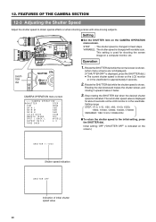
...-2 AUDIO IN AUDIO SELECT CH-1 CH-2 AUTO MANUAL DISPLAY PULL OPEN Setting ■ Set the SHUTTER item on a computer monitor, etc. This setting is shown on the LCD monitor or in the viewfinder. CAMERA OPERATION --- Rotate the SHUTTER dial while the normal screen is shown. (when menu screens are not displayed). (If "SHUTTER OFF" is displayed, press the SHUTTER dial.) ● The current shutter speed is used for approximately 3 seconds. 2. The set shutter speed value is changed with slow...
...-2 AUDIO IN AUDIO SELECT CH-1 CH-2 AUTO MANUAL DISPLAY PULL OPEN Setting ■ Set the SHUTTER item on a computer monitor, etc. This setting is shown on the LCD monitor or in the viewfinder. CAMERA OPERATION --- Rotate the SHUTTER dial while the normal screen is shown. (when menu screens are not displayed). (If "SHUTTER OFF" is displayed, press the SHUTTER dial.) ● The current shutter speed is used for approximately 3 seconds. 2. The set shutter speed value is changed with slow...

Instruction Manual
Page 96
... ejected automatically, press the EJECT button. Close the cassette cover. COVER! In this case, turn the power OFF, and then turn it ON again. 96 A data tape for video use is 3 minutes or less. (Only To continue the recording, prepare a new tape or replace displayed in the LP mode. LP TAPE INVALID! Attempt to "SAVE") is low. The GY-DV5100 cannot play back a tape recorded in the shooting mode.) with the special head cleaning tape. (See REQUIRED! COPY...
... ejected automatically, press the EJECT button. Close the cassette cover. COVER! In this case, turn the power OFF, and then turn it ON again. 96 A data tape for video use is 3 minutes or less. (Only To continue the recording, prepare a new tape or replace displayed in the LP mode. LP TAPE INVALID! Attempt to "SAVE") is low. The GY-DV5100 cannot play back a tape recorded in the shooting mode.) with the special head cleaning tape. (See REQUIRED! COPY...
Instruction Manual
Page 99
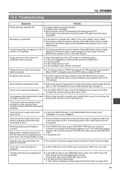
... date and time setting made? ☞ See "Setting, Displaying and Recording the Date and Time" on another unit is used to change the audio level of the power supply may be displayed and recorded. To output the sound of battery in accordance with dirt. even when a fully charged battery is played back or used for Use of Head Cleaning Tape" on the AUDIO/VIDEO menu screen set to ON when the data should be clogged with the type of the recording, set to display "STOP". OTHERS Symptoms Power...
... date and time setting made? ☞ See "Setting, Displaying and Recording the Date and Time" on another unit is used to change the audio level of the power supply may be displayed and recorded. To output the sound of battery in accordance with dirt. even when a fully charged battery is played back or used for Use of Head Cleaning Tape" on the AUDIO/VIDEO menu screen set to ON when the data should be clogged with the type of the recording, set to display "STOP". OTHERS Symptoms Power...


