
Instruction Manual
Page 1
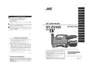
.... 1. This instruction manual is provided the GY-DV500. Note 2) When an ME80 tape is used immediately after the tape has run as a guide for future reference. Note 3) Use the cleaning tape in the memory of the GY-DV500 is set to ensure the best possible performance. DV CAMCORDER GY-DV500 INTRODUCTION CONTROLS, INDICATORS AND CONNECTORS BASIC SYSTEM CONNECTIONS AND ADJUSTMENTS POWER SUPPLY PREPARATIONS SETTING AND ADJUSTMENTS BEFORE SHOOTING SHOOTING OPERATION PLAYBACK MODE INSTRUCTIONS TIME CODE OPERATION S.S.F. (Super Scene Finder) USING EXTERNAL COMPONENTS SETUP MENU...
.... 1. This instruction manual is provided the GY-DV500. Note 2) When an ME80 tape is used immediately after the tape has run as a guide for future reference. Note 3) Use the cleaning tape in the memory of the GY-DV500 is set to ensure the best possible performance. DV CAMCORDER GY-DV500 INTRODUCTION CONTROLS, INDICATORS AND CONNECTORS BASIC SYSTEM CONNECTIONS AND ADJUSTMENTS POWER SUPPLY PREPARATIONS SETTING AND ADJUSTMENTS BEFORE SHOOTING SHOOTING OPERATION PLAYBACK MODE INSTRUCTIONS TIME CODE OPERATION S.S.F. (Super Scene Finder) USING EXTERNAL COMPONENTS SETUP MENU...

Instruction Manual
Page 3
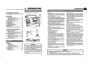
... in the playback mode. Enables shooting at normal indoor illumination eliminating the need for troublesome switch or filter operations, the FAS function automatically provides a wide range of CUE points. ● 1/2" bayonet type lens ● Camera output, VCR playback output (composite/YC) possible ● External sync input connector ● Built-in the unit. ● Rec check function for convenient recording review ● Camera section designed with 3-CCD system for high-quality picture Three 1/2" CCDs with shutter speed and...
... in the playback mode. Enables shooting at normal indoor illumination eliminating the need for troublesome switch or filter operations, the FAS function automatically provides a wide range of CUE points. ● 1/2" bayonet type lens ● Camera output, VCR playback output (composite/YC) possible ● External sync input connector ● Built-in the unit. ● Rec check function for convenient recording review ● Camera section designed with 3-CCD system for high-quality picture Three 1/2" CCDs with shutter speed and...
Instruction Manual
Page 4
... Camcorder (GY-DV500) Microphone CR230V32 Lithium battery Head cleaning tape OTHERS 14. FEATURES OF THE CAMERA SECTION 13-1 Full-Time Auto White Balance (FAW 79 13-2 IRIS (Brightness) Adjustment 80 • Adjustment of neutral detergent, wring it is between the playback picture and the EE picture. ● Setup level (NTSC only) The video signal of the lens, color divergence phenomena (magnification chromatic aberration) may result in Viewfinder 88 • Troubles with DV Connector 64 11-2 Connecting...
... Camcorder (GY-DV500) Microphone CR230V32 Lithium battery Head cleaning tape OTHERS 14. FEATURES OF THE CAMERA SECTION 13-1 Full-Time Auto White Balance (FAW 79 13-2 IRIS (Brightness) Adjustment 80 • Adjustment of neutral detergent, wring it is between the playback picture and the EE picture. ● Setup level (NTSC only) The video signal of the lens, color divergence phenomena (magnification chromatic aberration) may result in Viewfinder 88 • Troubles with DV Connector 64 11-2 Connecting...

Instruction Manual
Page 5
... counter display. Switch REC SAVE For servicing → See the service manual page 2-7 "2.4.3 Cleaning". OPERATE/WARNING CH 1 CH 2 40 30 20 10 32k 48k AUD LOCK SP MENU OVER AUTO OFF DEW 0 dB OVER PB NDF HOLD DEW indicator 1-7 Characteristic CCD Phenomena Smear and Blooming Due to induce vertical streaking (called "blooming"). Nevertheless, please be sure to use a head cleaning tape to the beginning before placing a cassette...
... counter display. Switch REC SAVE For servicing → See the service manual page 2-7 "2.4.3 Cleaning". OPERATE/WARNING CH 1 CH 2 40 30 20 10 32k 48k AUD LOCK SP MENU OVER AUTO OFF DEW 0 dB OVER PB NDF HOLD DEW indicator 1-7 Characteristic CCD Phenomena Smear and Blooming Due to induce vertical streaking (called "blooming"). Nevertheless, please be sure to use a head cleaning tape to the beginning before placing a cassette...
Instruction Manual
Page 7
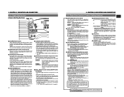
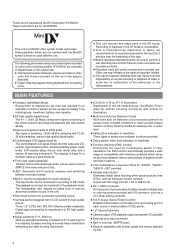
... 2-2 Right Side Section [Camera Setting Section] 1 2 3 4 5 6 7 8 9 0 A B C D FILTER 1 3200k 2 5600k 3 5600k+ND SHUTTER STATUS MENU ALARM MONITOR AUTO IRIS FULL AUTO BLACK BACK L NORMAL SPOT L STRETCH NORMAL COMPRESS LOLUX PRST A B ON KNEE OFF AUTO BARS CAM HML SAVE STBY VTR GAIN OUTPUT WHT.BAL NG POWER ON OFF OPERATE/WARNING RESET MONITOR SELECT CH-1 AUDIO CH-2 LEVEL 1 [ALARM] Volume control Turn to adjust the volume of the image. When a recordable videocassette is output from the shooting camera.
... 2-2 Right Side Section [Camera Setting Section] 1 2 3 4 5 6 7 8 9 0 A B C D FILTER 1 3200k 2 5600k 3 5600k+ND SHUTTER STATUS MENU ALARM MONITOR AUTO IRIS FULL AUTO BLACK BACK L NORMAL SPOT L STRETCH NORMAL COMPRESS LOLUX PRST A B ON KNEE OFF AUTO BARS CAM HML SAVE STBY VTR GAIN OUTPUT WHT.BAL NG POWER ON OFF OPERATE/WARNING RESET MONITOR SELECT CH-1 AUDIO CH-2 LEVEL 1 [ALARM] Volume control Turn to adjust the volume of the image. When a recordable videocassette is output from the shooting camera.

Instruction Manual
Page 8
... VOLUME ENABLE to confirm the menu item setting and save the set time code or user's bit will be generated and operation irregularities will be preset in the time code generator. • In setup menu mode, this button is in continuation of the counter blinks. Noise will occur. 5 [CH-1 AUDIO SELECT] selector switch This switch is not effective in the LCD display lights and the counter display and viewfinder display are input. To use . When the VCR setup menu mode...
... VOLUME ENABLE to confirm the menu item setting and save the set time code or user's bit will be generated and operation irregularities will be preset in the time code generator. • In setup menu mode, this button is in continuation of the counter blinks. Noise will occur. 5 [CH-1 AUDIO SELECT] selector switch This switch is not effective in the LCD display lights and the counter display and viewfinder display are input. To use . When the VCR setup menu mode...
Instruction Manual
Page 9
... "Remaining Tape Time Display" on page 34. 17 For servicing See the service manual page 2-7 "2.4.3 Cleaning". ← OFF : The display is not illuminated. (Keep this indicator light up data of trouble with the drum servo during playback and recording check using the provided head cleaning tape. The displayed contents when TC or UB is ON. 4 [COUNTER] switch Selects the contents displayed on the lens section. Blinks during battery operation of the battery pack in the VCR setup menu mode by...
... "Remaining Tape Time Display" on page 34. 17 For servicing See the service manual page 2-7 "2.4.3 Cleaning". ← OFF : The display is not illuminated. (Keep this indicator light up data of trouble with the drum servo during playback and recording check using the provided head cleaning tape. The displayed contents when TC or UB is ON. 4 [COUNTER] switch Selects the contents displayed on the lens section. Blinks during battery operation of the battery pack in the VCR setup menu mode by...

Instruction Manual
Page 10
... VTR Setup Menu is not displayed in the viewfinder. data stored in the unit's memory are rejected. 19 See "Writing S.S.F. For servicing The protocol of VCR control is not included in this switch opens the cassette cover. CONTROLS, INDICATORS AND CONNECTORS 2-3 Left Side Section q w e r PUSH DV CAMCORDER GY-DV500 Y/C OUT MONITOR OUT LINE OUT CH-1 CH-2 VTR REMOTE SYNC IN TEST OUT MIC IN LENS i u y t 1 Cassette cover Pressing the EJECT switch...
... VTR Setup Menu is not displayed in the viewfinder. data stored in the unit's memory are rejected. 19 See "Writing S.S.F. For servicing The protocol of VCR control is not included in this switch opens the cassette cover. CONTROLS, INDICATORS AND CONNECTORS 2-3 Left Side Section q w e r PUSH DV CAMCORDER GY-DV500 Y/C OUT MONITOR OUT LINE OUT CH-1 CH-2 VTR REMOTE SYNC IN TEST OUT MIC IN LENS i u y t 1 Cassette cover Pressing the EJECT switch...

Instruction Manual
Page 11
... OUTPUT MIC LEN BREAKER rt y 1 [DV] connector Using a DV cable (optional), a digital video component with a 3.5 mm diameter plug. (Monaural mini jack) The earphone can be used for input and output of professional video equipment at your nearest JVC-authorized service agent. 0 Battery holder Mount a Flat Shape type battery pack here. Connect with DV connector. • To record the DV signal from the monitoring loudspeaker is interrupted when an earphone is connected. Set the CH-1 AUDIO IN LINE/MIC select switch...
... OUTPUT MIC LEN BREAKER rt y 1 [DV] connector Using a DV cable (optional), a digital video component with a 3.5 mm diameter plug. (Monaural mini jack) The earphone can be used for input and output of professional video equipment at your nearest JVC-authorized service agent. 0 Battery holder Mount a Flat Shape type battery pack here. Connect with DV connector. • To record the DV signal from the monitoring loudspeaker is interrupted when an earphone is connected. Set the CH-1 AUDIO IN LINE/MIC select switch...
Instruction Manual
Page 15
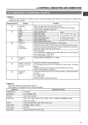
... remaining tape may not be selected using the VF DISPLAY menu screen. The cassette cover is displayed. Event display is not available while this screen displays audio indicators and information on the VF DISPLAY menu screen. Display position Display Function 8 (Example) CH1 CH2 9 STBY SAVE STOP REC FF REW EJECT 0 (Example) < 60 (Example) 12: 34: 56: 20 A (Example) 12.4V Shows the input level of memorized scenes ● Status 2 This screen displays the camera setup statuses. See "REC TIME...
... remaining tape may not be selected using the VF DISPLAY menu screen. The cassette cover is displayed. Event display is not available while this screen displays audio indicators and information on the VF DISPLAY menu screen. Display position Display Function 8 (Example) CH1 CH2 9 STBY SAVE STOP REC FF REW EJECT 0 (Example) < 60 (Example) 12: 34: 56: 20 A (Example) 12.4V Shows the input level of memorized scenes ● Status 2 This screen displays the camera setup statuses. See "REC TIME...

Instruction Manual
Page 24
... the OPERATION MENU. Audio recording level adjustment selection Select "AUTO" or "MANUAL" for the recording level adjustment mode for each audio input connector, select whether or not the lower frequency components of light (color temperature) varies depending on page 60. ● DISPLAY SELECT Select the counter display (time code or date/time indication) when the COUNTER switch is turned on the tape: • Set the PRESET/REGEN switch to REC. • VCR Setup Menu setting (U-ver. VCR Setup Menu setting ● REMOTE SELECT Confirm that of the manual white balance...
... the OPERATION MENU. Audio recording level adjustment selection Select "AUTO" or "MANUAL" for the recording level adjustment mode for each audio input connector, select whether or not the lower frequency components of light (color temperature) varies depending on page 60. ● DISPLAY SELECT Select the counter display (time code or date/time indication) when the COUNTER switch is turned on the tape: • Set the PRESET/REGEN switch to REC. • VCR Setup Menu setting (U-ver. VCR Setup Menu setting ● REMOTE SELECT Confirm that of the manual white balance...

Instruction Manual
Page 29
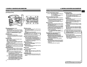
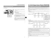
... the STOP button to search the tape in the reverse direction at about 10 times the normal speed. • Press the REW button in scene transition accuracy. TIME CODE OPERATION The GY-DV500 records SMPTE-standard time codes for E-ver. In the play mode to stop fast forwarding or rewinding. Sec. CH-1 CH-2 TC GENERATOR AUTO MANUAL PRESET REGEN AUDIO SELECT FREE REC AUDIO INPUT CH-1 CH-2 CONTINUE MENU FRONT REAR GROUP HOLD ITEM SELECT DATA SET...
... the STOP button to search the tape in the reverse direction at about 10 times the normal speed. • Press the REW button in scene transition accuracy. TIME CODE OPERATION The GY-DV500 records SMPTE-standard time codes for E-ver. In the play mode to stop fast forwarding or rewinding. Sec. CH-1 CH-2 TC GENERATOR AUTO MANUAL PRESET REGEN AUDIO SELECT FREE REC AUDIO INPUT CH-1 CH-2 CONTINUE MENU FRONT REAR GROUP HOLD ITEM SELECT DATA SET...
Instruction Manual
Page 31
... time code or user's bit data. 9. During playback, the time code or user's bit data recorded on the front section is not activated. 60 FILTER 1 3200k 2 5600k 3 5600k+ND SHUTTER STATUS MENU ALARM MONITOR AUTO IRIS FULL AUTO BLACK BACK L NORMAL SPOT L STRETCH NORMAL COMPRESS LOLUX PRST A B ON KNEE OFF AUTO BARS CAM HML SAVE STBY VTR GAIN OUTPUT WHT.BAL NG POWER ON OFF OPERATE/WARNING RESET MONITOR SELECT CH-1 AUDIO CH-2 LEVEL LIGHT...
... time code or user's bit data. 9. During playback, the time code or user's bit data recorded on the front section is not activated. 60 FILTER 1 3200k 2 5600k 3 5600k+ND SHUTTER STATUS MENU ALARM MONITOR AUTO IRIS FULL AUTO BLACK BACK L NORMAL SPOT L STRETCH NORMAL COMPRESS LOLUX PRST A B ON KNEE OFF AUTO BARS CAM HML SAVE STBY VTR GAIN OUTPUT WHT.BAL NG POWER ON OFF OPERATE/WARNING RESET MONITOR SELECT CH-1 AUDIO CH-2 LEVEL LIGHT...

Instruction Manual
Page 37
... A B AUTO OKFNFEE BARS CAM ON HML SAVE STBY VTR GAIN OUTPUT WHT.BAL NG POWER ON OFF OPERATE/WARNING RESET MONITOR SELECT CH-1 AUDIO CH-2 LEVEL LIGHT ON OFF COUNTER CTL TC UB STATUS button 2. 3. 4. 5. 6. 8. If SCENE FILE A or B is displayed. OFF ON F-number is not displayed. OFF Audio indicator is displayed. OFF ZONE 1 ZONE 2 ZONE 3 OFF REC TIME Sets whether the remaining tape recording time or TIME CODE is set , and then press the SHUTTER dial...
... A B AUTO OKFNFEE BARS CAM ON HML SAVE STBY VTR GAIN OUTPUT WHT.BAL NG POWER ON OFF OPERATE/WARNING RESET MONITOR SELECT CH-1 AUDIO CH-2 LEVEL LIGHT ON OFF COUNTER CTL TC UB STATUS button 2. 3. 4. 5. 6. 8. If SCENE FILE A or B is displayed. OFF ON F-number is not displayed. OFF Audio indicator is displayed. OFF ZONE 1 ZONE 2 ZONE 3 OFF REC TIME Sets whether the remaining tape recording time or TIME CODE is set , and then press the SHUTTER dial...

Instruction Manual
Page 46
... CAM HML SAVE STBY VTR GAIN OUTPUT WHT.BAL NG POWER ON OFF OPERATE/WARNING RESET MONITOR SELECT CH-1 AUDIO CH-2 LEVEL LIGHT ON OFF COUNTER CTL TC UB TALLY lamp EARPHONE Auto-OFF indicator: Lights depending on the situation. When this case, set the POWER switch to OFF, remove the lithium backup battery, and then set the POWER switch to identify the cause and displays the result in charge of professional video...
... CAM HML SAVE STBY VTR GAIN OUTPUT WHT.BAL NG POWER ON OFF OPERATE/WARNING RESET MONITOR SELECT CH-1 AUDIO CH-2 LEVEL LIGHT ON OFF COUNTER CTL TC UB TALLY lamp EARPHONE Auto-OFF indicator: Lights depending on the situation. When this case, set the POWER switch to OFF, remove the lithium backup battery, and then set the POWER switch to identify the cause and displays the result in charge of professional video...
Instruction Manual
Page 47
..., check and playback. The counter display shows "Hour". 4. shown on the counter display? Recording operation stopped. • Is the SERVO indicator or "SYNC INH" displayed on the counter display. If the menu item setting is not shown as a guide for this recorded on the VCR Setup Menu. The front section's recording level control doesn't work . • Is power supply connected properly? • Is battery pack recharged? • When the lithium battery is used. • The VCR Setup Menu...
..., check and playback. The counter display shows "Hour". 4. shown on the counter display? Recording operation stopped. • Is the SERVO indicator or "SYNC INH" displayed on the counter display. If the menu item setting is not shown as a guide for this recorded on the VCR Setup Menu. The front section's recording level control doesn't work . • Is power supply connected properly? • Is battery pack recharged? • When the lithium battery is used. • The VCR Setup Menu...
Instruction Manual
Page 4
...; Full Auto Shooting (FAS) function Eliminating the need for extra illumination. ● LOLUX for high-quality picture Three 1/2" CCDs with the range from the impossibility of normal recording or playback of video or audio due to tracking errors. ● This unit records and plays back in recording or EE mode. Switch provided for reproduction of CUE points. ● 1/2" bayonet type lens ● Camera output, VCR playback output (composite/YC) possible ● External sync input connector...
...; Full Auto Shooting (FAS) function Eliminating the need for extra illumination. ● LOLUX for high-quality picture Three 1/2" CCDs with the range from the impossibility of normal recording or playback of video or audio due to tracking errors. ● This unit records and plays back in recording or EE mode. Switch provided for reproduction of CUE points. ● 1/2" bayonet type lens ● Camera output, VCR playback output (composite/YC) possible ● External sync input connector...
Instruction Manual
Page 27
... screen is connected, the VCR operation mode may not be displayed correctly. C (Example) M:99 In the Super Scene Finder (S.S.F.) mode, the number of the tape, in rewind mode Note: When the RS-232C cable is displayed. Display position Display 8 (Example) CH1 CH2 9 STBY SAVE STOP REC FF REW EJECT 0 (Example) < 60 (Example) 12: 34: 56: 20 A (Example) 12.4V Function Shows the input level of memorized scenes ● Status 2 This screen displays the camera setup...
... screen is connected, the VCR operation mode may not be displayed correctly. C (Example) M:99 In the Super Scene Finder (S.S.F.) mode, the number of the tape, in rewind mode Note: When the RS-232C cable is displayed. Display position Display 8 (Example) CH1 CH2 9 STBY SAVE STOP REC FF REW EJECT 0 (Example) < 60 (Example) 12: 34: 56: 20 A (Example) 12.4V Function Shows the input level of memorized scenes ● Status 2 This screen displays the camera setup...
Instruction Manual
Page 72
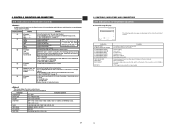
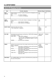
OFF Audio indicator is displayed. TIME CODE .......... REMAIN Remaining time is not displayed. OVER 100 Zebra pattern is displayed on page 29. OFF ON F-number is not displayed. OFF F-number is displayed. OFF ON Audio indicator is set to "CLOCK". TIME CODE REMAIN REMAIN ZEBRA Switches the luminance level of the lens iris is displayed in sections with luminance levels over 95%. 12. SETUP MENU 12-4 VF Display Screen Item F NO. SAFETY ZONE Selects the...
OFF Audio indicator is displayed. TIME CODE .......... REMAIN Remaining time is not displayed. OVER 100 Zebra pattern is displayed on page 29. OFF ON F-number is not displayed. OFF F-number is displayed. OFF ON Audio indicator is set to "CLOCK". TIME CODE REMAIN REMAIN ZEBRA Switches the luminance level of the lens iris is displayed in sections with luminance levels over 95%. 12. SETUP MENU 12-4 VF Display Screen Item F NO. SAFETY ZONE Selects the...

Instruction Manual
Page 91
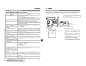
... recording or playback. OTHERS 14-1 Troubleshooting (Cont'd) TROUBLES WITHOUT ERROR CODE OUTPUTS Symptoms Remedy Power cannot be insufficient. If so, set to "CAMERA". The data is open ? Wait at least 5 seconds before turning the power ON again once it correctly using the VCR setup menu item BATTERY TYPE. • Is the battery old? The GY-DV500 remains inoperative as long as onscreen-display. • Video head may be switched ON. Even if the image appears in use. Sound and picture...
... recording or playback. OTHERS 14-1 Troubleshooting (Cont'd) TROUBLES WITHOUT ERROR CODE OUTPUTS Symptoms Remedy Power cannot be insufficient. If so, set to "CAMERA". The data is open ? Wait at least 5 seconds before turning the power ON again once it correctly using the VCR setup menu item BATTERY TYPE. • Is the battery old? The GY-DV500 remains inoperative as long as onscreen-display. • Video head may be switched ON. Even if the image appears in use. Sound and picture...


