Instruction Manual
Page 3
... or power circuits, or where it can result in a risk of the polarized plug. (B) Your product may be sure the antenna or cable system is left unattended and unused for ventilation. To ensure reliable operation of the product and to replace your obsolete outlet. Power Lines An ...outside antenna or cable system is connected to assure your product dealer or local power company. This product has been engineered and manufactured to the product, be ...
... or power circuits, or where it can result in a risk of the polarized plug. (B) Your product may be sure the antenna or cable system is left unattended and unused for ventilation. To ensure reliable operation of the product and to replace your obsolete outlet. Power Lines An ...outside antenna or cable system is connected to assure your product dealer or local power company. This product has been engineered and manufactured to the product, be ...
Instruction Manual
Page 5
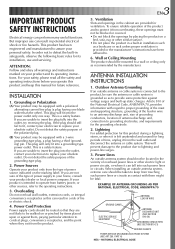
...result in dropping the unit, or in a malfunction. Take care not to the camcorder. make sure you only use a tripod on the cables will cause the camcorder to this camcorder is not recommended, as a show, perform- Carrying or holding the camcorder by the viewfinder and/or... finger caught in damage. Ⅲ This camcorder is designed exclusively for personal enjoyment, it is prohibited. (Even if you obtain permis- Connecting cables (Audio/Video, S-Video, Editing, DC, etc.) to always securely attach and use without proper permission is strongly recommended that you record an...
...result in dropping the unit, or in a malfunction. Take care not to the camcorder. make sure you only use a tripod on the cables will cause the camcorder to this camcorder is not recommended, as a show, perform- Carrying or holding the camcorder by the viewfinder and/or... finger caught in damage. Ⅲ This camcorder is designed exclusively for personal enjoyment, it is prohibited. (Even if you obtain permis- Connecting cables (Audio/Video, S-Video, Editing, DC, etc.) to always securely attach and use without proper permission is strongly recommended that you record an...
Instruction Manual
Page 32
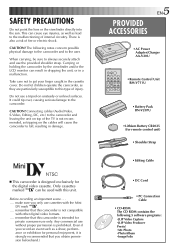
... R The connectors are located beneath the cover. Yellow: Not connected Yellow: Not connected White to Audio Output L Audio/Video cable (optional) To TV or VCR White to AUDIO L IN Red to Audio Output R Red to your VCR and TV instruction... of connections. AA. C.onnCeoctnionn etoctaioTVn otroVaCRTeVquoiprpeVdCwRitheqanuSip-VpIDeEdO wINiathndaAn/VS-inVpIuDt EO INconannecdtoArs/V input connectors Use optional S-Video and Audio cables. To S-Video Output S-Video cable (optional) To S-VIDEO IN TV VCR B. When making the connections, refer also to AUDIO R IN The connectors are...
... R The connectors are located beneath the cover. Yellow: Not connected Yellow: Not connected White to Audio Output L Audio/Video cable (optional) To TV or VCR White to AUDIO L IN Red to Audio Output R Red to your VCR and TV instruction... of connections. AA. C.onnCeoctnionn etoctaioTVn otroVaCRTeVquoiprpeVdCwRitheqanuSip-VpIDeEdO wINiathndaAn/VS-inVpIuDt EO INconannecdtoArs/V input connectors Use optional S-Video and Audio cables. To S-Video Output S-Video cable (optional) To S-VIDEO IN TV VCR B. When making the connections, refer also to AUDIO R IN The connectors are...
Instruction Manual
Page 34
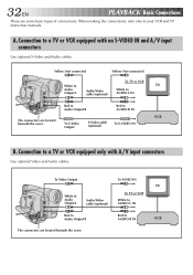
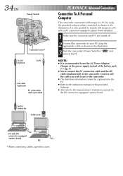
...instruction manual for the DV connector-equipped capture board. 34 EN Power Switch Connector cover* To DV IN/OUT To PC DV cable (optional) PC connection cable (provided) To DV connector To RS-232C PLAYBACK Advanced Connections Connection To A Personal Computer This camcorder can transfer still images to ... " and NOTES: ● It is also possible to transfer still images to a PC with DV connector-equipped capture board PC * When connecting cables, open this cover. It is recommended to use to the camcorder. ● The date/time information cannot be captured into the PC. ●...
...instruction manual for the DV connector-equipped capture board. 34 EN Power Switch Connector cover* To DV IN/OUT To PC DV cable (optional) PC connection cable (provided) To DV connector To RS-232C PLAYBACK Advanced Connections Connection To A Personal Computer This camcorder can transfer still images to ... " and NOTES: ● It is also possible to transfer still images to a PC with DV connector-equipped capture board PC * When connecting cables, open this cover. It is recommended to use to the camcorder. ● The date/time information cannot be captured into the PC. ●...
Instruction Manual
Page 35
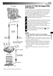
...2668; pg. 7). ● For Digital Dubbing, this cover. This camcorder can be used as shown in the illustration. 3 If necessary, connect the PC connection cable (provided) to the printer's PC connector and the PC's RS-232C connector. 4 Turn the camcorder's Power Switch to " turn on an effect similar to ...the connected units. It is recommended to one device at a time. To DV IN connector Power Switch Connector cover* To DV IN/OUT DV cable (optional) To DV connector Video unit equipped with a DV input connector To PC connector EN35 Connection To A Video Unit Equipped With A DV ...
...2668; pg. 7). ● For Digital Dubbing, this cover. This camcorder can be used as shown in the illustration. 3 If necessary, connect the PC connection cable (provided) to the printer's PC connector and the PC's RS-232C connector. 4 Turn the camcorder's Power Switch to " turn on an effect similar to ...the connected units. It is recommended to one device at a time. To DV IN connector Power Switch Connector cover* To DV IN/OUT DV cable (optional) To DV connector Video unit equipped with a DV input connector To PC connector EN35 Connection To A Video Unit Equipped With A DV ...
Instruction Manual
Page 36
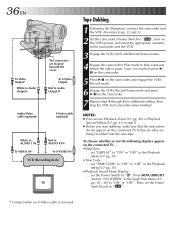
..." in the Playback Menu (੬ pg. 30). •Playback Sound Mode Display .... To S-Video Output Red to Audio Output R Audio/Video cable (optional) S-Video cable (optional) White to AUDIO L IN Red to Audio Output L The connectors are being recorded onto the new tape. Also refer to pg. 32...the camcorder and the VCR. 3 Engage the VCR's AUX and Record-Pause modes. 4 Engage the camcorder's Play mode to " ". * Connect when an S-Video cable is reached, press 4/ 6 on the camcorder. 5 Press 4/6 on the camcorder and engage the VCR's Record mode. 6 Engage the VCR's Record-Pause mode ...
..." in the Playback Menu (੬ pg. 30). •Playback Sound Mode Display .... To S-Video Output Red to Audio Output R Audio/Video cable (optional) S-Video cable (optional) White to AUDIO L IN Red to Audio Output L The connectors are being recorded onto the new tape. Also refer to pg. 32...the camcorder and the VCR. 3 Engage the VCR's AUX and Record-Pause modes. 4 Engage the camcorder's Play mode to " ". * Connect when an S-Video cable is reached, press 4/ 6 on the camcorder. 5 Press 4/6 on the camcorder and engage the VCR's Record mode. 6 Engage the VCR's Record-Pause mode ...
Instruction Manual
Page 37
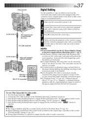
...If the remote control is connected correctly, sometimes the image may stop so that an unusual image is not dubbed. ● Even though the DV cable is used as the power supply instead of the current "SOUND MODE" setting (੬ pg. 20). ● During Digital Dubbing, no signals are... from the spot on the screen. 4. Press the Recording Start/Stop button again to start recording. Power Switch To DV IN/OUT The connectors are JVC video units, both units. ● For Digital Dubbing, this occurs, turn off . 2 Connect the camcorder to your video unit equipped with a DV connector...
...If the remote control is connected correctly, sometimes the image may stop so that an unusual image is not dubbed. ● Even though the DV cable is used as the power supply instead of the current "SOUND MODE" setting (੬ pg. 20). ● During Digital Dubbing, no signals are... from the spot on the screen. 4. Press the Recording Start/Stop button again to start recording. Power Switch To DV IN/OUT The connectors are JVC video units, both units. ● For Digital Dubbing, this occurs, turn off . 2 Connect the camcorder to your video unit equipped with a DV connector...
Instruction Manual
Page 43
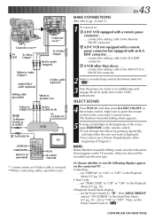
...pg. 30). •Time Code .... set the Power Switch back to : A JVC VCR equipped with an R.A. MAKE CONNECTIONS Also refer to the R.A.EDIT connector. EN43 1 To connect to " ". EDIT connector . . . ... connect the editing cable to pg. 32 and 33. The Random Assemble Editing Menu appears. 5 If ...Display .... A VCR other than above . . . ... If they do not appear on the connected TV . . . • Date/Time .... connect the editing cable to the RM-V711U's PAUSE IN connector. 2 Insert a recorded tape and set "TIME CODE" to "ON" or "OFF". SELECT SCENES 4 Press PLAY (4) and ...
...pg. 30). •Time Code .... set the Power Switch back to : A JVC VCR equipped with an R.A. MAKE CONNECTIONS Also refer to the R.A.EDIT connector. EN43 1 To connect to " ". EDIT connector . . . ... connect the editing cable to pg. 32 and 33. The Random Assemble Editing Menu appears. 5 If ...Display .... A VCR other than above . . . ... If they do not appear on the connected TV . . . • Date/Time .... connect the editing cable to the RM-V711U's PAUSE IN connector. 2 Insert a recorded tape and set "TIME CODE" to "ON" or "OFF". SELECT SCENES 4 Press PLAY (4) and ...
Instruction Manual
Page 45
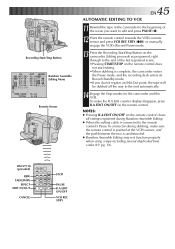
... deck enters its Record-Standby mode. •If you want to the remote control's Pause In connector during Random Assemble Editing. ● When the editing cable is unobstructed. ● Random Assemble Editing may not function properly when using a tape including several duplicated time codes (੬ pg. 16). NOTES: ● Pressing R.A.EDIT...
... deck enters its Record-Standby mode. •If you want to the remote control's Pause In connector during Random Assemble Editing. ● When the editing cable is unobstructed. ● Random Assemble Editing may not function properly when using a tape including several duplicated time codes (੬ pg. 16). NOTES: ● Pressing R.A.EDIT...
Instruction Manual
Page 53
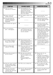
...monitor indications are jittery. 35. Images on again, then operate it does, you repeat the above two or three times, please consult your nearest JVC dealer. 38. •To protect the battery, it is recommended to 180 degrees, open at the bottom of some kind has occurred. POSSIBLE ...of over 45 degrees. • The LCD monitor's brightness setting is too dark. 41. •This is not a malfunction. 42. •The DV cable was plugged/ unplugged with power turned on . 40. •The lens cap is attached. •␣ The LCD monitor is not available. An error ...
...monitor indications are jittery. 35. Images on again, then operate it does, you repeat the above two or three times, please consult your nearest JVC dealer. 38. •To protect the battery, it is recommended to 180 degrees, open at the bottom of some kind has occurred. POSSIBLE ...of over 45 degrees. • The LCD monitor's brightness setting is too dark. 41. •This is not a malfunction. 42. •The DV cable was plugged/ unplugged with power turned on . 40. •The lens cap is attached. •␣ The LCD monitor is not available. An error ...
Instruction Manual
Page 59
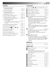
...standard. a sensor necessary for products compliant with a J terminal. For further details, consult your nearest JVC dealer. •JLIP-controlled editing from the camcorder to a VCR is not possible if the VCR is...IN Connector pg. 7 q J Terminal [JLIP (Joint Level Interface Protocol) Connector pg. 43 •Connect the editing cable when performing Random Assemble Editing (੬ pg. 42 - 47). •It is used to connect the camcorder to cover... Lamp pg. 13 Other Parts t Battery Pack Mount pg. 7 y •Camera Sensor Be careful not to the serial port of a personal computer.
...standard. a sensor necessary for products compliant with a J terminal. For further details, consult your nearest JVC dealer. •JLIP-controlled editing from the camcorder to a VCR is not possible if the VCR is...IN Connector pg. 7 q J Terminal [JLIP (Joint Level Interface Protocol) Connector pg. 43 •Connect the editing cable when performing Random Assemble Editing (੬ pg. 42 - 47). •It is used to connect the camcorder to cover... Lamp pg. 13 Other Parts t Battery Pack Mount pg. 7 y •Camera Sensor Be careful not to the serial port of a personal computer.


