User Manual
Page 7
... guidelines 23 Handling static-sensitive devices 24 Major components of the xSeries 206 Type 8482 and 8487 server 25 Removing the side cover 26 Removing the bezel 27 Removing and installing the support bracket 28 Installing a memory module 29 Installing a drive 31 Installing a drive in bay ...Boot Menu program 11 Chapter 3. Introduction 1 Related documentation 1 Notices and statements used in bay 5, 6, or 7 36 © Copyright IBM Corp. 2004, 2007 v Diagnostics 13 General checkout 13 Diagnostic tools overview 15 Power-on self-test 15 POST beep codes 15 POST error...
... guidelines 23 Handling static-sensitive devices 24 Major components of the xSeries 206 Type 8482 and 8487 server 25 Removing the side cover 26 Removing the bezel 27 Removing and installing the support bracket 28 Installing a memory module 29 Installing a drive 31 Installing a drive in bay ...Boot Menu program 11 Chapter 3. Introduction 1 Related documentation 1 Notices and statements used in bay 5, 6, or 7 36 © Copyright IBM Corp. 2004, 2007 v Diagnostics 13 General checkout 13 Diagnostic tools overview 15 Power-on self-test 15 POST beep codes 15 POST error...
User Manual
Page 11
...memory and data management. v Installation Guide This printed document contains instructions for installing some options. v Safety Information This document is in PDF on the IBM xSeries Documentation CD. The documentation might have features that are available from the IBM Web site at http://www.ibm.com/eserver/xseries...updates might be available to a service technician. It is in PDF on the IBM xSeries Documentation CD. Chapter 1. Introduction The IBM xSeries 206 Type 8482 and 8487 server is not included in Portable Document Format (PDF). It contains instructions for ...
...memory and data management. v Installation Guide This printed document contains instructions for installing some options. v Safety Information This document is in PDF on the IBM xSeries Documentation CD. The documentation might have features that are available from the IBM Web site at http://www.ibm.com/eserver/xseries...updates might be available to a service technician. It is in PDF on the IBM xSeries Documentation CD. Chapter 1. Introduction The IBM xSeries 206 Type 8482 and 8487 server is not included in Portable Document Format (PDF). It contains instructions for ...
User Manual
Page 13
...drive: SATA or SCSI v One of the following drives: - CD-RW: IDE - hard disk drive bays with 16 MB SDRAM video memory on the server model, some features might not be available, or some specifications might exceed the average values stated because of drives: - ...Compatible with SVGA and VGA - 16 MB video memory Diagnostic LEDs: v Fans v Memory v Microprocessor Acoustical noise emissions: v Sound power, idling: 5.3 bel v Sound power, operating: 5.5 bel PCI expansion slots: v Two PCI-X...
...drive: SATA or SCSI v One of the following drives: - CD-RW: IDE - hard disk drive bays with 16 MB SDRAM video memory on the server model, some features might not be available, or some specifications might exceed the average values stated because of drives: - ...Compatible with SVGA and VGA - 16 MB video memory Diagnostic LEDs: v Fans v Memory v Microprocessor Acoustical noise emissions: v Sound power, idling: 5.3 bel v Sound power, operating: 5.5 bel PCI expansion slots: v Two PCI-X...
User Manual
Page 17
The server can also be turned on in the server, the server can turn off the server. The amount of memory that is reserved for various system resources and is reserved for system resources depends on the operating system, the configuration of the server, and the ... Approximately 20 seconds after the server is not turned on from the power source. v If the server is installed in any of memory (physical or logical) is installed, some memory is unavailable to an Advanced System Management (ASM) interconnect network that the server is connected to an ac power source but is...
The server can also be turned on in the server, the server can turn off the server. The amount of memory that is reserved for various system resources and is reserved for system resources depends on the operating system, the configuration of the server, and the ... Approximately 20 seconds after the server is not turned on from the power source. v If the server is installed in any of memory (physical or logical) is installed, some memory is unavailable to an Advanced System Management (ASM) interconnect network that the server is connected to an ac power source but is...
User Manual
Page 29
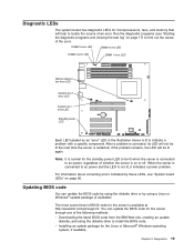
... is on page 17) to find out the cause of the error. Diagnostic LEDs The system board has diagnostic LEDs for microprocessors, fans, and memory that will help to install the BIOS code. v Installing an update package for the server through one of whether the server is connected to indicate...the LED will be lit when the server is connected to ac power, regardless of the following methods: v Downloading the latest BIOS code from the IBM Web site, creating an update diskette, and using the diskette drive or by these LEDs, see "Starting the diagnostic programs and viewing the test log...
... is on page 17) to find out the cause of the error. Diagnostic LEDs The system board has diagnostic LEDs for microprocessors, fans, and memory that will help to install the BIOS code. v Installing an update package for the server through one of whether the server is connected to indicate...the LED will be lit when the server is connected to ac power, regardless of the following methods: v Downloading the latest BIOS code from the IBM Web site, creating an update diskette, and using the diskette drive or by these LEDs, see "Starting the diagnostic programs and viewing the test log...
User Manual
Page 31
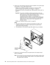
Erasing a lost or forgotten password (clearing CMOS memory) This section applies to a power source, keyboard, monitor, and mouse. 10. The illustration in "Recovering from pins 1 and 2 to the jumper. Connect the server to ...
Erasing a lost or forgotten password (clearing CMOS memory) This section applies to a power source, keyboard, monitor, and mouse. 10. The illustration in "Recovering from pins 1 and 2 to the jumper. Connect the server to ...
User Manual
Page 38
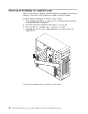
... the following steps to access the device. Read "Installation guidelines" on page 107. 2. To reinstall the support bracket, reverse the previous steps. 28 xSeries 206 Type 8482 and 8487: Hardware Maintenance Manual and Troubleshooting Guide Remove the side cover ("Removing the side cover" on the rear end of the support bracket from the...176; angle. 4. Pull out on page 26). 3. Removing and installing the support bracket When working with some devices, such as hard disk drives, adapters, and memory modules, you must first remove the support bracket to remove the support bracket: 1.
... the following steps to access the device. Read "Installation guidelines" on page 107. 2. To reinstall the support bracket, reverse the previous steps. 28 xSeries 206 Type 8482 and 8487: Hardware Maintenance Manual and Troubleshooting Guide Remove the side cover ("Removing the side cover" on the rear end of the support bracket from the...176; angle. 4. Pull out on page 26). 3. Removing and installing the support bracket When working with some devices, such as hard disk drives, adapters, and memory modules, you must first remove the support bracket to remove the support bracket: 1.
User Manual
Page 39
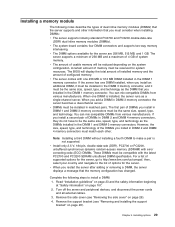
...DIMM without installing a fourth DIMM to make a pair is installed, the server runs as the DIMM that you install in the DIMM 1 memory connector. Installing options 29 For a list of supported options for the server. Read "Installation guidelines" on page 23 and the safety information beginning... bracket" on the system configuration. However, the size, speed, type, and technology of options for the server, go to http://www.ibm.com/us/compat/; Remove the support bracket (see "Removing the side cover" on page 107. 2. You can mix compatible DIMMs from various...
...DIMM without installing a fourth DIMM to make a pair is installed, the server runs as the DIMM that you install in the DIMM 1 memory connector. Installing options 29 For a list of supported options for the server. Read "Installation guidelines" on page 23 and the safety information beginning... bracket" on the system configuration. However, the size, speed, type, and technology of options for the server, go to http://www.ibm.com/us/compat/; Remove the support bracket (see "Removing the side cover" on page 107. 2. You can mix compatible DIMMs from various...
User Manual
Page 40
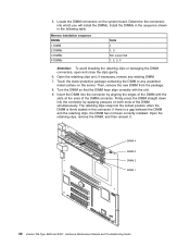
... installed. The retaining clips snap into the connector by aligning the edges of the DIMM simultaneously. DIMM 4 DIMM 3 DIMM 2 DIMM 1 30 xSeries 206 Type 8482 and 8487: Hardware Maintenance Manual and Troubleshooting Guide Memory installation sequence DIMMs 1 DIMM 2 DIMMs 3 DIMMs 4 DIMMs Slots 1 1, 3 Not supported 1, 2, 3, 4 Attention: To avoid breaking the retaining clips or damaging the...
... installed. The retaining clips snap into the connector by aligning the edges of the DIMM simultaneously. DIMM 4 DIMM 3 DIMM 2 DIMM 1 30 xSeries 206 Type 8482 and 8487: Hardware Maintenance Manual and Troubleshooting Guide Memory installation sequence DIMMs 1 DIMM 2 DIMMs 3 DIMMs 4 DIMMs Slots 1 1, 3 Not supported 1, 2, 3, 4 Attention: To avoid breaking the retaining clips or damaging the...
User Manual
Page 44
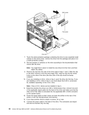
... into the back of the drive and make sure that it on the system board. 12. drive in . then, connect one way. 34 xSeries 206 Type 8482 and 8487: Hardware Maintenance Manual and Troubleshooting Guide If you have another drive to remove it easier to the 3.5-in bay 4. 11. drive. Determine whether... . Remove the clip from the package and place it does not block the airflow to the back of the drives or over the microprocessor and memory. 13. Connect the power cable to the rear of the drive. The connectors are installing a 3.5-in. Route the signal cable so that the ...
... into the back of the drive and make sure that it on the system board. 12. drive in . then, connect one way. 34 xSeries 206 Type 8482 and 8487: Hardware Maintenance Manual and Troubleshooting Guide If you have another drive to remove it easier to the 3.5-in bay 4. 11. drive. Determine whether... . Remove the clip from the package and place it does not block the airflow to the back of the drives or over the microprocessor and memory. 13. Connect the power cable to the rear of the drive. The connectors are installing a 3.5-in. Route the signal cable so that the ...
User Manual
Page 51
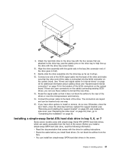
... cable to help line up the drive with the guide rails in the bay (the connector end of the drives or over the microprocessor and memory. 14. v You can install two simple-swap SATA hard disk drives in first). 11. Chapter 4. Attach the hard disk drive to connect the new drive...
... cable to help line up the drive with the guide rails in the bay (the connector end of the drives or over the microprocessor and memory. 14. v You can install two simple-swap SATA hard disk drives in first). 11. Chapter 4. Attach the hard disk drive to connect the new drive...
User Manual
Page 84
...v Microprocessor and fan sink assembly (see "Microprocessor and fan sink" on page 29). If replacement adhesive material is removed. 74 xSeries 206 Type 8482 and 8487: Hardware Maintenance Manual and Troubleshooting Guide v DIMMs (see "SCSI mini-PCI-X adapter" on the system board when the system board ... static-protective place: v Adapters (see "Installing an adapter" on page 44), including the SCSI mini-PCI-X adapter (see "Installing a memory module" on page 67). If any of existing adhesive material from your ability to the chassis and put them before applying the new adhesive ...
...v Microprocessor and fan sink assembly (see "Microprocessor and fan sink" on page 29). If replacement adhesive material is removed. 74 xSeries 206 Type 8482 and 8487: Hardware Maintenance Manual and Troubleshooting Guide v DIMMs (see "SCSI mini-PCI-X adapter" on the system board when the system board ... static-protective place: v Adapters (see "Installing an adapter" on page 44), including the SCSI mini-PCI-X adapter (see "Installing a memory module" on page 67). If any of existing adhesive material from your ability to the chassis and put them before applying the new adhesive ...
User Manual
Page 89
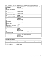
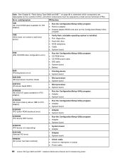
... retry. System board. v System board Chapter 7. DIMM 2. v System board 3-3-3 (No memory installed) 1. No-beep symptoms Note: See Chapter 8, "Parts listing, Type 8482 and 8487," on page 99 to determine which components are replaceable by the customer (CRU), and which ...-FRU index 79 System board 3-2-1 (Serial port failed) v System board 3-2-2 (Parallel port failed) v System board 3-2-4 (Failure comparing CMOS memory size against actual) 1. DIMM 2. system believed operable) v System board 3-1-1 (Timer tick interrupt failed) v System board 3-1-2 (Interval timer channel...
... retry. System board. v System board Chapter 7. DIMM 2. v System board 3-3-3 (No memory installed) 1. No-beep symptoms Note: See Chapter 8, "Parts listing, Type 8482 and 8487," on page 99 to determine which components are replaceable by the customer (CRU), and which ...-FRU index 79 System board 3-2-1 (Serial port failed) v System board 3-2-2 (Parallel port failed) v System board 3-2-4 (Failure comparing CMOS memory size against actual) 1. DIMM 2. system believed operable) v System board 3-1-1 (Timer tick interrupt failed) v System board 3-1-2 (Interval timer channel...
User Manual
Page 90
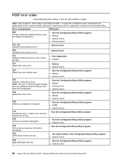
..., 102 (System and processor error) v System board 106 (System and processor error) v System board 114 (Adapter read-only memory error (check 55 AA)) 1. System board 161 (Real time clock battery error) 1. System board. 162 (Device configuration error...Run the Configuration/Setup Utility program. 2. Battery. 3. System board. 80 xSeries 206 Type 8482 and 8487: Hardware Maintenance Manual and Troubleshooting Guide Run the Configuration/Setup Utility program. 2. System board. 164 (Memory configuration changed.) 1. Set serial number in the Configuration/Setup Utility program. ...
..., 102 (System and processor error) v System board 106 (System and processor error) v System board 114 (Adapter read-only memory error (check 55 AA)) 1. System board 161 (Real time clock battery error) 1. System board. 162 (Device configuration error...Run the Configuration/Setup Utility program. 2. Battery. 3. System board. 80 xSeries 206 Type 8482 and 8487: Hardware Maintenance Manual and Troubleshooting Guide Run the Configuration/Setup Utility program. 2. System board. 164 (Memory configuration changed.) 1. Set serial number in the Configuration/Setup Utility program. ...
User Manual
Page 91
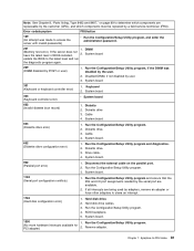
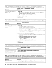
... 602 (Invalid diskette boot record) 1. Diskette drive. 3. Hard disk drive cables. 3. SCSI backplane. 5. Chapter 7. Note: See Chapter 8, "Parts listing, Type 8482 and 8487," on the parallel port. 2. DIMM (Memory test error.) If the server does not have the latest level of BIOS installed, 2. Diskette drive 3. System board 301 (Keyboard or keyboard controller...
... 602 (Invalid diskette boot record) 1. Diskette drive. 3. Hard disk drive cables. 3. SCSI backplane. 5. Chapter 7. Note: See Chapter 8, "Parts listing, Type 8482 and 8487," on the parallel port. 2. DIMM (Memory test error.) If the server does not have the latest level of BIOS installed, 2. Diskette drive 3. System board 301 (Keyboard or keyboard controller...
User Manual
Page 92
... CD-ROM drive. 3. System board. 6. Pointing device 2. Adapter. 3. Adapter. 3. Check for PCI adapter) 1. Power cable. 82 xSeries 206 Type 8482 and 8487: Hardware Maintenance Manual and Troubleshooting Guide Verify that a startable operating system is installed. 2. SCSI backplane. 5. Battery. 8603 (Pointing-device error... which components must be replaced by a field service technician (FRU). Error code/symptom FRU/action 1801 (No more memory above 1MB for PCI adapter) 1. Disable adapter BIOS code and run the Configuration/Setup Utility program. 1962 (Drive does...
... CD-ROM drive. 3. System board. 6. Pointing device 2. Adapter. 3. Adapter. 3. Check for PCI adapter) 1. Power cable. 82 xSeries 206 Type 8482 and 8487: Hardware Maintenance Manual and Troubleshooting Guide Verify that a startable operating system is installed. 2. SCSI backplane. 5. Battery. 8603 (Pointing-device error... which components must be replaced by a field service technician (FRU). Error code/symptom FRU/action 1801 (No more memory above 1MB for PCI adapter) 1. Disable adapter BIOS code and run the Configuration/Setup Utility program. 1962 (Drive does...

User Manual
Page 94
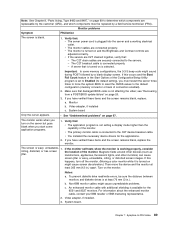
... 035-XXX-s99 1. Verify BIOS code is installed and seated correctly. 2. See error text for more information. 2. System board. 206-XXX-000 (Failed diskette drive test) 1. Cable. 3. Rerun the test using another CD-ROM. 2. CD-ROM drive. 4. ...using another diskette. 2. System board. 84 xSeries 206 Type 8482 and 8487: Hardware Maintenance Manual and Troubleshooting Guide Obtain the basic and extended configuration status and see error text) 1. Cable 3. Microprocessor 1. 4. System board. 201-XXX-0nn (Failed memory test.) 1. Microprocessor 2. 4. Microprocessor 2....
... 035-XXX-s99 1. Verify BIOS code is installed and seated correctly. 2. See error text for more information. 2. System board. 206-XXX-000 (Failed diskette drive test) 1. Cable. 3. Rerun the test using another CD-ROM. 2. CD-ROM drive. 4. ...using another diskette. 2. System board. 84 xSeries 206 Type 8482 and 8487: Hardware Maintenance Manual and Troubleshooting Guide Obtain the basic and extended configuration status and see error text) 1. Cable 3. Microprocessor 1. 4. System board. 201-XXX-0nn (Failed memory test.) 1. Microprocessor 2. 4. Microprocessor 2....
User Manual
Page 98
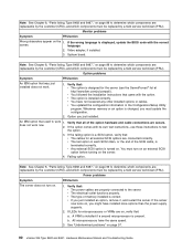
... been manually disabled. 2. v If the DIMM was disabled by a field service technician (FRU). c. DIMM. 4. Verify that : v The memory modules are seated properly. Monitor problems Symptom FRU/action Testing the monitor. Verify that: v The mouse or pointing-device cable is seated properly. ... does not work. 1. Check POST error log for adjusting and testing instructions. (Some IBM monitors have their own self-tests.) 88 xSeries 206 Type 8482 and 8487: Hardware Maintenance Manual and Troubleshooting Guide Save the configuration and restart the server. 3.
... been manually disabled. 2. v If the DIMM was disabled by a field service technician (FRU). c. DIMM. 4. Verify that : v The memory modules are seated properly. Monitor problems Symptom FRU/action Testing the monitor. Verify that: v The mouse or pointing-device cable is seated properly. ... does not work. 1. Check POST error log for adjusting and testing instructions. (Some IBM monitors have their own self-tests.) 88 xSeries 206 Type 8482 and 8487: Hardware Maintenance Manual and Troubleshooting Guide Save the configuration and restart the server. 3.
User Manual
Page 99
... or IBM marketing representative. 2. Chapter 7. v The monitor cables are C2T chained together, verify that: - The C2T chain cables are securely connected to -FRU index 89 If you start some memory configurations, the 3-3-3 beep code might cause unpredictable problems. c. Video adapter, if installed c.... Verify that : v The application program is available for the applications. 2. Note: See Chapter 8, "Parts listing, Type 8482 and 8487," on page 99 to determine which components are replaceable by the customer (CRU), and which components must restart the server three times to ...
... or IBM marketing representative. 2. Chapter 7. v The monitor cables are C2T chained together, verify that: - The C2T chain cables are securely connected to -FRU index 89 If you start some memory configurations, the 3-3-3 beep code might cause unpredictable problems. c. Video adapter, if installed c.... Verify that : v The application program is available for the applications. 2. Note: See Chapter 8, "Parts listing, Type 8482 and 8487," on page 99 to determine which components are replaceable by the customer (CRU), and which components must restart the server three times to ...
User Manual
Page 100
...FRU). Monitor problems Symptom FRU/action Wrong characters appear on page 97. 90 xSeries 206 Type 8482 and 8487: Hardware Maintenance Manual and Troubleshooting Guide System board. v The option is a ...have not loosened any other installed options or cables. If the wrong language is correct. Whenever memory or an option is present. A VRM is installed if a second microprocessor is changed, you ...that : v The cables for the server (see the ServerProven® list at http://www.ibm.com/pc/compat/). Video adapter, if installed. 3. Option you must be replaced by a ...
...FRU). Monitor problems Symptom FRU/action Wrong characters appear on page 97. 90 xSeries 206 Type 8482 and 8487: Hardware Maintenance Manual and Troubleshooting Guide System board. v The option is a ...have not loosened any other installed options or cables. If the wrong language is correct. Whenever memory or an option is present. A VRM is installed if a second microprocessor is changed, you ...that : v The cables for the server (see the ServerProven® list at http://www.ibm.com/pc/compat/). Video adapter, if installed. 3. Option you must be replaced by a ...


