
User Manual
Page 8
... System board LEDs 85 Error symptoms 86 Service processor error codes 92 ServeRAID error codes 92 POST (ISPR) error procedures 93 SCSI error codes 96 Undetermined problems 97 Problem determination tips 98 vi xSeries 206 Type 8482 and 8487: Hardware Maintenance Manual and Troubleshooting Guide SCSI IDs for hot-swap hard disk drives 39 Installing a non-hot-swap SCSI hard disk drive in bay 4, 5, 6, or 7 . . . . . 39 Installing a simple-swap Serial ATA hard disk drive in bay 5, 6, or 7 . . . . 41 Power and signal cables for internal drives 43 Installing an adapter 44 Cabling an optional...
... System board LEDs 85 Error symptoms 86 Service processor error codes 92 ServeRAID error codes 92 POST (ISPR) error procedures 93 SCSI error codes 96 Undetermined problems 97 Problem determination tips 98 vi xSeries 206 Type 8482 and 8487: Hardware Maintenance Manual and Troubleshooting Guide SCSI IDs for hot-swap hard disk drives 39 Installing a non-hot-swap SCSI hard disk drive in bay 4, 5, 6, or 7 . . . . . 39 Installing a simple-swap Serial ATA hard disk drive in bay 5, 6, or 7 . . . . 41 Power and signal cables for internal drives 43 Installing an adapter 44 Cabling an optional...
User Manual
Page 11
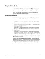
.../eserver/xseries/. It contains information to help a user solve problems or to provide helpful information to -date information about the server. Related documentation This Hardware Maintenance Manual and Troubleshooting Guide is in the documentation that the server supports. The server might be included on IBM X-Architecture® technologies. These updates are not described in PDF on the IBM xSeries Documentation CD. v Installation Guide This printed document contains instructions for setting up -to a service...
.../eserver/xseries/. It contains information to help a user solve problems or to provide helpful information to -date information about the server. Related documentation This Hardware Maintenance Manual and Troubleshooting Guide is in the documentation that the server supports. The server might be included on IBM X-Architecture® technologies. These updates are not described in PDF on the IBM xSeries Documentation CD. v Installation Guide This printed document contains instructions for setting up -to a service...
User Manual
Page 13
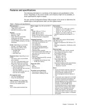
... on the system board. removable-media drive bays (one CD-ROM drive installed) v Two 3.5-in use the Configuration/Setup Utility program in . Non-hot-swap bays with RJ-45 Ethernet port v Two serial ports v One parallel port v Dual port Serial ATA controller v One internal Ultra320 SCSI port (mini-PCI slot) v Integrated RAID capability v Four Universal Serial Bus (USB) v2.0 ports (two on front and two on rear) v Keyboard port v Mouse port v ATA-100 single-channel IDE controller v ATI 7000M video - Server on the number and type of room...
... on the system board. removable-media drive bays (one CD-ROM drive installed) v Two 3.5-in use the Configuration/Setup Utility program in . Non-hot-swap bays with RJ-45 Ethernet port v Two serial ports v One parallel port v Dual port Serial ATA controller v One internal Ultra320 SCSI port (mini-PCI slot) v Integrated RAID capability v Four Universal Serial Bus (USB) v2.0 ports (two on front and two on rear) v Keyboard port v Mouse port v ATA-100 single-channel IDE controller v ATI 7000M video - Server on the number and type of room...
User Manual
Page 16
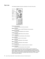
...installed in PCI-X slot 2, the server has additional connectors and LEDs. Mouse connector Connect a mouse or other PS/2 device to this connector to connect the server to this connector. Keyboard connector Connect a PS/2 keyboard to a network. USB 2 connector Connect a USB device to this connector. Serial 2 connector Connect a 9-pin serial device to this connector. Parallel connector Connect a parallel device to the optional Remote Supervisor Adapter II. 6 xSeries 206 Type 8482 and 8487: Hardware Maintenance Manual and Troubleshooting Guide If you must disconnect the video cable...
...installed in PCI-X slot 2, the server has additional connectors and LEDs. Mouse connector Connect a mouse or other PS/2 device to this connector to connect the server to this connector. Keyboard connector Connect a PS/2 keyboard to a network. USB 2 connector Connect a USB device to this connector. Serial 2 connector Connect a 9-pin serial device to this connector. Parallel connector Connect a parallel device to the optional Remote Supervisor Adapter II. 6 xSeries 206 Type 8482 and 8487: Hardware Maintenance Manual and Troubleshooting Guide If you must disconnect the video cable...
User Manual
Page 19
... use this program to start this utility, see "Using the Configuration/Setup Utility program." The following steps to configure serial-port and parallel-port assignments, change the drive startup sequence, set the date and time, and set passwords. Detailed information about the Adaptec® HostRAID™ configuration programs, see "Configuring your server" in the User's Guide on the IBM xSeries Documentation CD. For more information about ServeRAID Manager is part of the basic input/output system (BIOS) code...
... use this program to start this utility, see "Using the Configuration/Setup Utility program." The following steps to configure serial-port and parallel-port assignments, change the drive startup sequence, set the date and time, and set passwords. Detailed information about the Adaptec® HostRAID™ configuration programs, see "Configuring your server" in the User's Guide on the IBM xSeries Documentation CD. For more information about ServeRAID Manager is part of the basic input/output system (BIOS) code...
User Manual
Page 20
... Troubleshooting Guide Turn on the IBM xSeries Documentation CD. Using ServeRAID Manager Use the ServeRAID Manager program to access the full Configuration/Setup Utility menu. 3. From the Configuration/Setup Utility main menu, select Devices and I/O Ports and press Enter. 4. Follow the instructions on the IBM xSeries Documentation CD. Select System Board Ethernet PXE/DHCP and use these programs as a startable device, and you must type the administrator password to : v Configure arrays v View your RAID configuration and associated devices v Monitor operation of independent disks...
... Troubleshooting Guide Turn on the IBM xSeries Documentation CD. Using ServeRAID Manager Use the ServeRAID Manager program to access the full Configuration/Setup Utility menu. 3. From the Configuration/Setup Utility main menu, select Devices and I/O Ports and press Enter. 4. Follow the instructions on the IBM xSeries Documentation CD. Select System Board Ethernet PXE/DHCP and use these programs as a startable device, and you must type the administrator password to : v Configure arrays v View your RAID configuration and associated devices v Monitor operation of independent disks...
User Manual
Page 24
... maintenance for LEDs (see "Error symptoms" on the server. 8. Run the storage test. Go to the middle position. 6. If the system-error log indicates a damaged field replaceable unit (FRU), replace the FRU, and run the diagnostic programs to -FRU index," on page 80). 9. If the xSeries 206 server has an optional Remote Supervisor Adapter II, check the service processor system-error logs: a. b. Turn on page 86. 14 xSeries 206 Type 8482 and 8487: Hardware Maintenance Manual and Troubleshooting Guide YES...
... maintenance for LEDs (see "Error symptoms" on the server. 8. Run the storage test. Go to the middle position. 6. If the system-error log indicates a damaged field replaceable unit (FRU), replace the FRU, and run the diagnostic programs to -FRU index," on page 80). 9. If the xSeries 206 server has an optional Remote Supervisor Adapter II, check the service processor system-error logs: a. b. Turn on page 86. 14 xSeries 206 Type 8482 and 8487: Hardware Maintenance Manual and Troubleshooting Guide YES...

User Manual
Page 28
... the hardware passes the Enhanced Diagnostics but the problem persists during normal server operations, a software error might appear when you exit from the diagnostic programs, the test log is not installed. 18 xSeries 206 Type 8482 and 8487: Hardware Maintenance Manual and Troubleshooting Guide If you exit from the diagnostic programs, the test log is cleared. Note: If the server does not have definite symptoms (see "SCSI error codes" on a diskette or to the hard disk if...
... the hardware passes the Enhanced Diagnostics but the problem persists during normal server operations, a software error might appear when you exit from the diagnostic programs, the test log is not installed. 18 xSeries 206 Type 8482 and 8487: Hardware Maintenance Manual and Troubleshooting Guide If you exit from the diagnostic programs, the test log is cleared. Note: If the server does not have definite symptoms (see "SCSI error codes" on a diskette or to the hard disk if...
User Manual
Page 29
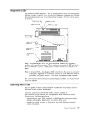
...://www.ibm.com/pc/support/. v Installing an update package for the server is restarted; Diagnostic LEDs The system board has diagnostic LEDs for the server through one of the following methods: v Downloading the latest BIOS code from the IBM Web site, creating an update diskette, and using the diskette drive to install the BIOS code. Run the diagnostic programs (see "System board LEDs" on page 17) to locate the source of the error. if the problem remains, the LED...
...://www.ibm.com/pc/support/. v Installing an update package for the server is restarted; Diagnostic LEDs The system board has diagnostic LEDs for the server through one of the following methods: v Downloading the latest BIOS code from the IBM Web site, creating an update diskette, and using the diskette drive to install the BIOS code. Run the diagnostic programs (see "System board LEDs" on page 17) to locate the source of the error. if the problem remains, the LED...

User Manual
Page 30
... xSeries 206 Type 8482 and 8487: Hardware Maintenance Manual and Troubleshooting Guide Remove the diskette from pins 1 and 2. 7. Turn on the server to recover: 1. Boot block jumper (JP1) CMOS jumper (JP2) 6. then, reconnect all power cords and external cables; If this diskette from http://www.ibm.com/pc/support/. 10. Remove the side cover and support bracket (see "Removing and installing the support bracket" on page 28 and "Replacing the side cover" on page 50). 8. Remove the boot block recovery jumper from the diskette drive...
... xSeries 206 Type 8482 and 8487: Hardware Maintenance Manual and Troubleshooting Guide Remove the diskette from pins 1 and 2. 7. Turn on the server to recover: 1. Boot block jumper (JP1) CMOS jumper (JP2) 6. then, reconnect all power cords and external cables; If this diskette from http://www.ibm.com/pc/support/. 10. Remove the side cover and support bracket (see "Removing and installing the support bracket" on page 28 and "Replacing the side cover" on page 50). 8. Remove the boot block recovery jumper from the diskette drive...
User Manual
Page 31
... old password or set the CMOS recovery jumper and erase a forgotten password: 1. Replace any adapters that were removed; If you do not change or delete the password, the next time you start the server one time without having to use the user password, and use the Configuration/Setup Utility program to set a new user password. Connect the server to pins 1 and 2 8. Select Save Settings and press Enter. Locate the CMOS recovery jumper (JP2) on the system board. 6. then, return the CMOS recovery jumper to a power source, keyboard, monitor, and mouse. 10...
... old password or set the CMOS recovery jumper and erase a forgotten password: 1. Replace any adapters that were removed; If you do not change or delete the password, the next time you start the server one time without having to use the user password, and use the Configuration/Setup Utility program to set a new user password. Connect the server to pins 1 and 2 8. Select Save Settings and press Enter. Locate the CMOS recovery jumper (JP2) on the system board. 6. then, return the CMOS recovery jumper to a power source, keyboard, monitor, and mouse. 10...
User Manual
Page 45
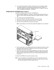
... of the server. 7. Chapter 4. Replacing the CD-ROM drive in the direction of the drive. If you are installing a new CD-ROM drive, read the instructions that the blue side of the clip is pointing toward the front of the arrow to be set . Disconnect all external cables. 4. Drive clip 6. Remove the clip from your hardware. Installing options 35 Turn off the server and all attached devices. 3. To install the CD-ROM drive, reverse...
... of the server. 7. Chapter 4. Replacing the CD-ROM drive in the direction of the drive. If you are installing a new CD-ROM drive, read the instructions that the blue side of the clip is pointing toward the front of the arrow to be set . Disconnect all external cables. 4. Drive clip 6. Remove the clip from your hardware. Installing options 35 Turn off the server and all attached devices. 3. To install the CD-ROM drive, reverse...
User Manual
Page 51
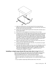
... 7 Some server models come with the drive for the location of this cable is connected into the SCSI connector on page 50); Installing options 41 Connect the power cable to the rear of the drive. v Route the cable before you can use the plastic pins on the system board. Route the signal cable so that comes with simple-swap Serial ATA (SATA) hard disk drives, which are keyed and can install two simple-swap SATA hard disk drives in first...
... 7 Some server models come with the drive for the location of this cable is connected into the SCSI connector on page 50); Installing options 41 Connect the power cable to the rear of the drive. v Route the cable before you can use the plastic pins on the system board. Route the signal cable so that comes with simple-swap Serial ATA (SATA) hard disk drives, which are keyed and can install two simple-swap SATA hard disk drives in first...
User Manual
Page 54
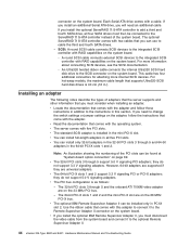
... adapters in this adapter to connect it to change the switch settings or jumper settings on the system board. - Use the ribbon cable that comes with RAID capabilities on the adapter, follow those instructions in the mini-PCI-X slot. If you install an additional Serial ATA drive, you will need to the optional Remote Supervisor Adapter II. 44 xSeries 206 Type 8482 and 8487: Hardware Maintenance Manual and Troubleshooting Guide A round SCSI cable connects external SCSI devices to the ServeRAID 7t S-ATA controller instead of adapters that the server supports...
... adapters in this adapter to connect it to change the switch settings or jumper settings on the system board. - Use the ribbon cable that comes with RAID capabilities on the adapter, follow those instructions in the mini-PCI-X slot. If you install an additional Serial ATA drive, you will need to the optional Remote Supervisor Adapter II. 44 xSeries 206 Type 8482 and 8487: Hardware Maintenance Manual and Troubleshooting Guide A round SCSI cable connects external SCSI devices to the ServeRAID 7t S-ATA controller instead of adapters that the server supports...
User Manual
Page 99
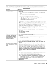
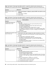
... service technician (FRU). Video adapter, if installed. 3. Note: See Chapter 8, "Parts listing, Type 8482 and 8487," on page 99 to determine which components are connected properly. Verify that: v The server power cord is connected to -FRU index 89 The C2T breakout cable is wavy, unreadable, 1. A server that : v The application program is not setting a display mode higher than the capability of the Configuration/Setup Utility program is turned on is blank. 1. The monitor works...
... service technician (FRU). Video adapter, if installed. 3. Note: See Chapter 8, "Parts listing, Type 8482 and 8487," on page 99 to determine which components are connected properly. Verify that: v The server power cord is connected to -FRU index 89 The C2T breakout cable is wavy, unreadable, 1. A server that : v The application program is not setting a display mode higher than the capability of the Configuration/Setup Utility program is turned on is blank. 1. The monitor works...
User Manual
Page 100
... replaced by a field service technician (FRU). If the option comes with the option. You must update the configuration. 2. Verify that used to work . 1. If the server now turns on, you just installed. If the wrong language is installed correctly. Failing option. Monitor problems Symptom FRU/action Wrong characters appear on page 97. 90 xSeries 206 Type 8482 and 8487: Hardware Maintenance Manual and Troubleshooting Guide Option problems Symptom FRU/action An IBM option that : a. v The last option in the Configuration/Setup Utility...
... replaced by a field service technician (FRU). If the option comes with the option. You must update the configuration. 2. Verify that used to work . 1. If the server now turns on, you just installed. If the wrong language is installed correctly. Failing option. Monitor problems Symptom FRU/action Wrong characters appear on page 97. 90 xSeries 206 Type 8482 and 8487: Hardware Maintenance Manual and Troubleshooting Guide Option problems Symptom FRU/action An IBM option that : a. v The last option in the Configuration/Setup Utility...
User Manual
Page 102
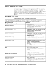
... of BIOS code and firmware for the service processor, see the system-error log (see "Starting the diagnostic programs and viewing the test log" on serve). 4xxx thru 5xxx (Code DRAM error) 1. Install download jumpers, flash latest level BIOS and firmware for controller. ServeRAID controller. 92 xSeries 206 Type 8482 and 8487: Hardware Maintenance Manual and Troubleshooting Guide Error code/symptom FRU/action 1xxx (Microcode checksum error) 1. Remove jumpers. 2. ServeRAID-5i controller. 4. Reseat daughter card. 2. Install download jumpers, flash latest level BIOS and firmware...
... of BIOS code and firmware for the service processor, see the system-error log (see "Starting the diagnostic programs and viewing the test log" on serve). 4xxx thru 5xxx (Code DRAM error) 1. Install download jumpers, flash latest level BIOS and firmware for controller. ServeRAID controller. 92 xSeries 206 Type 8482 and 8487: Hardware Maintenance Manual and Troubleshooting Guide Error code/symptom FRU/action 1xxx (Microcode checksum error) 1. Remove jumpers. 2. ServeRAID-5i controller. 4. Reseat daughter card. 2. Install download jumpers, flash latest level BIOS and firmware...

User Manual
Page 155
... LED 4 eject button 4 installing 31 problems 86 © Copyright IBM Corp. 2004, 2007 CD-ROM drive (continued) removing 35 chart, troubleshooting 18 checkout, general 13 checkout, procedure 14 components 25 system board 69 configuration parallel port 54 updating 51 Configuration/Setup Utility 9 connector battery 69 microprocessor 69 connectors adapter 69 cable 70 external port 71 external port connectors 71 input/output 53 internal cable 69, 70 memory 69 serial 55 serial port pin-assignments 55 system board 69 Ultra160 SCSI 55 universal serial bus (USB) 56 video...
... LED 4 eject button 4 installing 31 problems 86 © Copyright IBM Corp. 2004, 2007 CD-ROM drive (continued) removing 35 chart, troubleshooting 18 checkout, general 13 checkout, procedure 14 components 25 system board 69 configuration parallel port 54 updating 51 Configuration/Setup Utility 9 connector battery 69 microprocessor 69 connectors adapter 69 cable 70 external port 71 external port connectors 71 input/output 53 internal cable 69, 70 memory 69 serial 55 serial port pin-assignments 55 system board 69 Ultra160 SCSI 55 universal serial bus (USB) 56 video...
User Manual
Page 157
... 87 keyboard 87 memory 88 microprocessor 88 monitor 88 mouse 87, 88 option 90 pointing device 88 power 90 serial port 91 software 91 solving 13 R recovering POST/BIOS update failure 20 related publications 1 removable media drives, installing 31 removing bezel 27 CD-ROM drive 35 control panel assembly 63 diskette drive 36 front USB connector assembly 64 hard disk drive backplane 60 microprocessor and fan sink 67 power supply 65 rear fan 62 SCSI mini-PCI-X card 61 support bracket 28 system board 73 replace battery 48 cover 50...
... 87 keyboard 87 memory 88 microprocessor 88 monitor 88 mouse 87, 88 option 90 pointing device 88 power 90 serial port 91 software 91 solving 13 R recovering POST/BIOS update failure 20 related publications 1 removable media drives, installing 31 removing bezel 27 CD-ROM drive 35 control panel assembly 63 diskette drive 36 front USB connector assembly 64 hard disk drive backplane 60 microprocessor and fan sink 67 power supply 65 rear fan 62 SCSI mini-PCI-X card 61 support bracket 28 system board 73 replace battery 48 cover 50...
User Manual
Page 158
... devices, handling 24 status LEDs 4 support bracket, removing 28 switches and jumpers 73 system board connectors external port 71 internal cable 70 internal cables 69 SCSI 55 internal connectors SCSI 70 jumper blocks 73 LEDs 72 removing 73 system error LED 5 system reliability 23 universal serial bus (USB) (continued) ports 56 using Boot Menu program 11 the Adaptec HostRAID configuration programs 10 utility Configuration/Setup 9 utility program Intel 10 V video connector 57 video controller 3 W Web site compatible options 23 weight 3 T tape drive, installing 31 test log 18 viewing diagnostic...
... devices, handling 24 status LEDs 4 support bracket, removing 28 switches and jumpers 73 system board connectors external port 71 internal cable 70 internal cables 69 SCSI 55 internal connectors SCSI 70 jumper blocks 73 LEDs 72 removing 73 system error LED 5 system reliability 23 universal serial bus (USB) (continued) ports 56 using Boot Menu program 11 the Adaptec HostRAID configuration programs 10 utility Configuration/Setup 9 utility program Intel 10 V video connector 57 video controller 3 W Web site compatible options 23 weight 3 T tape drive, installing 31 test log 18 viewing diagnostic...


