
User Manual
Page 8
... Diagnostic error codes 83 System board LEDs 85 Error symptoms 86 Service processor error codes 92 ServeRAID error codes 92 POST (ISPR) error procedures 93 SCSI error codes 96 Undetermined problems 97 Problem determination tips 98 vi xSeries 206 Type 8482 and 8487: Hardware Maintenance Manual... panel assembly 63 Front USB connector assembly 64 Power supply 65 Microprocessor and fan sink 67 System board 69 System-board option connectors 69 System-board internal connectors 70 System-board external connectors 71 System-board LEDs 72 System-board switches and jumpers 73 System...
... Diagnostic error codes 83 System board LEDs 85 Error symptoms 86 Service processor error codes 92 ServeRAID error codes 92 POST (ISPR) error procedures 93 SCSI error codes 96 Undetermined problems 97 Problem determination tips 98 vi xSeries 206 Type 8482 and 8487: Hardware Maintenance Manual... panel assembly 63 Front USB connector assembly 64 Power supply 65 Microprocessor and fan sink 67 System board 69 System-board option connectors 69 System-board internal connectors 70 System-board external connectors 71 System-board LEDs 72 System-board switches and jumpers 73 System...
User Manual
Page 13
... 0 to 20.8 kg (45.8 lb) depending upon configuration Integrated functions: v Intel Ethernet controller on the system board with 16 MB SDRAM video memory on the system board. CD-ROM: IDE - bays (one CD-ROM drive installed) v Two 3.5-in accordance with one diskette drive ...voltage high range: - Open hot-swap bays - Minimum: 100 V ac - Introduction 3 Features and specifications The following information is on the system board Fans: Two or three speed-controlled fans Environment: v Air temperature: - Serial ATA (SATA) bays with one hard disk drive installed Power supply...
... 0 to 20.8 kg (45.8 lb) depending upon configuration Integrated functions: v Intel Ethernet controller on the system board with 16 MB SDRAM video memory on the system board. CD-ROM: IDE - bays (one CD-ROM drive installed) v Two 3.5-in accordance with one diskette drive ...voltage high range: - Open hot-swap bays - Minimum: 100 V ac - Introduction 3 Features and specifications The following information is on the system board Fans: Two or three speed-controlled fans Environment: v Air temperature: - Serial ATA (SATA) bays with one hard disk drive installed Power supply...
User Manual
Page 15
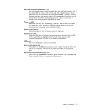
...faulty. Power-control button Press this LED is flashing, it indicates that the controller is off manually. See "System-board LEDs" on and off and still connected to an optional ServeRAID™ controller, a slowly flashing (one flash per second), it indicates that a system error has occurred. Ethernet link status... the status LED for additional information. Power-on LED When this LED is lit, it indicates that there is turned on the system board might also be lit to these connectors. When this LED is lit and not flashing, it indicates that the server is activity between the...
...faulty. Power-control button Press this LED is flashing, it indicates that the controller is off manually. See "System-board LEDs" on and off and still connected to an optional ServeRAID™ controller, a slowly flashing (one flash per second), it indicates that a system error has occurred. Ethernet link status... the status LED for additional information. Power-on LED When this LED is lit, it indicates that there is turned on the system board might also be lit to these connectors. When this LED is lit and not flashing, it indicates that the server is activity between the...
User Manual
Page 16
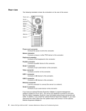
... this connector to connect the server to the optional Remote Supervisor Adapter II. 6 xSeries 206 Type 8482 and 8487: Hardware Maintenance Manual and Troubleshooting Guide Ethernet connector Use this connector. If you must disconnect the video cable from the system board and connect it to a network. Video connector Connect a monitor to this connector. Serial...
... this connector to connect the server to the optional Remote Supervisor Adapter II. 6 xSeries 206 Type 8482 and 8487: Hardware Maintenance Manual and Troubleshooting Guide Ethernet connector Use this connector. If you must disconnect the video cable from the system board and connect it to a network. Video connector Connect a monitor to this connector. Serial...
User Manual
Page 20
... the monitor screen. 2. Be sure to access the full Configuration/Setup Utility menu. 3. Complete the following steps to Enabled. 5. Select System Board Ethernet PXE/DHCP and use the Right Arrow (→) key to set , you can customize where the network startup option appears in the User...the server. For more information on using these programs and the most recent device-driver files are available at www.ibm.com/pc/support. 10 xSeries 206 Type 8482 and 8487: Hardware Maintenance Manual and Troubleshooting Guide Be sure to the integrated Serial ATA controller and the SCSI controller....
... the monitor screen. 2. Be sure to access the full Configuration/Setup Utility menu. 3. Complete the following steps to Enabled. 5. Select System Board Ethernet PXE/DHCP and use the Right Arrow (→) key to set , you can customize where the network startup option appears in the User...the server. For more information on using these programs and the most recent device-driver files are available at www.ibm.com/pc/support. 10 xSeries 206 Type 8482 and 8487: Hardware Maintenance Manual and Troubleshooting Guide Be sure to the integrated Serial ATA controller and the SCSI controller....
User Manual
Page 23
... diagnostic programs. 3. If the server is suspended and a POST error code is displayed, see "Diagnostic programs and error messages" on the IBM Enhanced Diagnostics CD. The failing server might be part of a cluster if any suite of the attached storage units is displayed, correct the .... 2004, 2007 13 The other error messages might occur with the server. v The diagnostic programs are part of the server: the system board, Ethernet controller, video controller, RAM, keyboard, mouse (pointing device), serial ports, hard disk drives, and parallel port. For intermittent problems,...
... diagnostic programs. 3. If the server is suspended and a POST error code is displayed, see "Diagnostic programs and error messages" on the IBM Enhanced Diagnostics CD. The failing server might be part of a cluster if any suite of the attached storage units is displayed, correct the .... 2004, 2007 13 The other error messages might occur with the server. v The diagnostic programs are part of the server: the system board, Ethernet controller, video controller, RAM, keyboard, mouse (pointing device), serial ports, hard disk drives, and parallel port. For intermittent problems,...
User Manual
Page 24
...following steps: 1. Run the diagnostic programs (see "Starting the diagnostic programs and viewing the test log" on page 77. Check the system board for the server. if these logs do not specify a particular error, go to the cluster. Check all external devices. 4. If you ... down all display controls to confirm that are displayed on page 86. 14 xSeries 206 Type 8482 and 8487: Hardware Maintenance Manual and Troubleshooting Guide Go to -FRU index," on page 17). If the xSeries 206 server has an optional Remote Supervisor Adapter II, check the service processor system...
...following steps: 1. Run the diagnostic programs (see "Starting the diagnostic programs and viewing the test log" on page 77. Check the system board for the server. if these logs do not specify a particular error, go to the cluster. Check all external devices. 4. If you ... down all display controls to confirm that are displayed on page 86. 14 xSeries 206 Type 8482 and 8487: Hardware Maintenance Manual and Troubleshooting Guide Go to -FRU index," on page 17). If the xSeries 206 server has an optional Remote Supervisor Adapter II, check the service processor system...
User Manual
Page 29
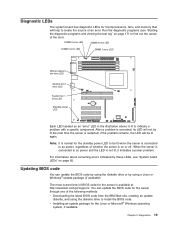
...For information about correcting errors indicated by using a Linux or Windows® update package (if available). Run the diagnostic programs (see "System board LEDs" on or off. v Installing an update package for the server is connected to indicate a problem with a specific component. Diagnostics 19 ...When the server is available at http://www.ibm.com/pc/support/. You can update the BIOS code by using the diskette drive to find out the cause of an error. Note...
...For information about correcting errors indicated by using a Linux or Windows® update package (if available). Run the diagnostic programs (see "System board LEDs" on or off. v Installing an update package for the server is connected to indicate a problem with a specific component. Diagnostics 19 ...When the server is available at http://www.ibm.com/pc/support/. You can update the BIOS code by using the diskette drive to find out the cause of an error. Note...

User Manual
Page 30
... this happens, complete the following illustration shows the location of the jumper on page 24. 2. Remove the diskette from http://www.ibm.com/pc/support/. 10. Disconnect the power cord and all power cords and external cables; Connect the server to pins 1 and...block recovery jumper to a power source, keyboard, monitor, and mouse. 9. Turn on the system board, removing any adapters that impede access to restart the operating system. 20 xSeries 206 Type 8482 and 8487: Hardware Maintenance Manual and Troubleshooting Guide After the update session is being updated (flash ...
... this happens, complete the following illustration shows the location of the jumper on page 24. 2. Remove the diskette from http://www.ibm.com/pc/support/. 10. Disconnect the power cord and all power cords and external cables; Connect the server to pins 1 and...block recovery jumper to a power source, keyboard, monitor, and mouse. 9. Turn on the system board, removing any adapters that impede access to restart the operating system. 20 xSeries 206 Type 8482 and 8487: Hardware Maintenance Manual and Troubleshooting Guide After the update session is being updated (flash ...
User Manual
Page 31
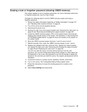
Review the safety information beginning at "Safety information" on page 107 and "Handling static-sensitive devices" on the system board. 6. Replace any adapters that were removed; Follow the instructions to set a new user password. Complete the following steps to erase the ...Wait 60 seconds; Select Save Settings and press Enter. then, return the CMOS recovery jumper to pins 1 and 2 8. Turn on the system board, removing any adapters that impede access to the jumper. Diagnostics 21 Erasing a lost or forgotten password (clearing CMOS memory) This section applies to lost...
Review the safety information beginning at "Safety information" on page 107 and "Handling static-sensitive devices" on the system board. 6. Replace any adapters that were removed; Follow the instructions to set a new user password. Complete the following steps to erase the ...Wait 60 seconds; Select Save Settings and press Enter. then, return the CMOS recovery jumper to pins 1 and 2 8. Turn on the system board, removing any adapters that impede access to the jumper. Diagnostics 21 Erasing a lost or forgotten password (clearing CMOS memory) This section applies to lost...
User Manual
Page 32
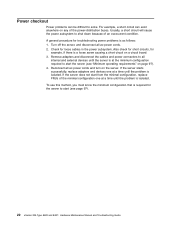
... power problems is isolated. Also check for short circuits, for the server to start the server (see page 97). 22 xSeries 206 Type 8482 and 8487: Hardware Maintenance Manual and Troubleshooting Guide If the server does not start from the minimal configuration, replace FRUs of the...example, a short circuit can be difficult to all internal and external devices until the problem is a loose screw causing a short circuit on a circuit board. 3. Usually, a short circuit will cause the power subsystem to start (see "Minimum operating requirements" on page 97). 4. If the server starts ...
... power problems is isolated. Also check for short circuits, for the server to start the server (see page 97). 22 xSeries 206 Type 8482 and 8487: Hardware Maintenance Manual and Troubleshooting Guide If the server does not start from the minimal configuration, replace FRUs of the...example, a short circuit can be difficult to all internal and external devices until the problem is a loose screw causing a short circuit on a circuit board. 3. Usually, a short circuit will cause the power subsystem to start (see "Minimum operating requirements" on page 97). 4. If the server starts ...
User Manual
Page 35
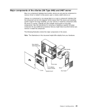
... adapterretaining bracket EMC shields Filler panels Cover Drive cage Front adaptersupport bracket System board Bezel Door hatch Chapter 4. Note: The illustrations in this document might differ slightly from or install it in the server. Major components of the xSeries 206 Type 8482 and 8487 server Blue on a component indicates touch points, where you can...
... adapterretaining bracket EMC shields Filler panels Cover Drive cage Front adaptersupport bracket System board Bezel Door hatch Chapter 4. Note: The illustrations in this document might differ slightly from or install it in the server. Major components of the xSeries 206 Type 8482 and 8487 server Blue on a component indicates touch points, where you can...
User Manual
Page 39
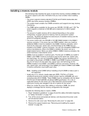
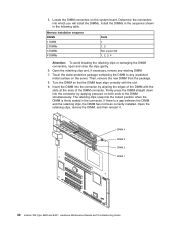
...a message that the memory configuration has changed. Remove the support bracket (see "Removing the side cover" on page 28). v The system board contains four DIMM connectors and supports two-way memory interleaving. The BIOS will be reduced depending on page 107. 2. The first pair of ...SDRAM) with the latest PC2700 and PC3200 SDRAM unbuffered DIMM specification. then, select your country and navigate to http://www.ibm.com/us/compat/; Read "Installation guidelines" on page 23 and the safety information beginning at "Safety information" on the system configuration. Chapter...
...a message that the memory configuration has changed. Remove the support bracket (see "Removing the side cover" on page 28). v The system board contains four DIMM connectors and supports two-way memory interleaving. The BIOS will be reduced depending on page 107. 2. The first pair of ...SDRAM) with the latest PC2700 and PC3200 SDRAM unbuffered DIMM specification. then, select your country and navigate to http://www.ibm.com/us/compat/; Read "Installation guidelines" on page 23 and the safety information beginning at "Safety information" on the system configuration. Chapter...
User Manual
Page 40
... the retaining clips, remove the DIMM, and then reinsert it. Open the retaining clips and, if necessary, remove any unpainted metal surface on the system board. Turn the DIMM so that the DIMM keys align correctly with the slots at the ends of the DIMM simultaneously. 5. Memory installation sequence DIMMs 1 DIMM... installed. Locate the DIMM connectors on the server. Touch the static-protective package containing the DIMM to any existing DIMM. 7. DIMM 4 DIMM 3 DIMM 2 DIMM 1 30 xSeries 206 Type 8482 and 8487: Hardware Maintenance Manual and Troubleshooting Guide
... the retaining clips, remove the DIMM, and then reinsert it. Open the retaining clips and, if necessary, remove any unpainted metal surface on the system board. Turn the DIMM so that the DIMM keys align correctly with the slots at the ends of the DIMM simultaneously. 5. Memory installation sequence DIMMs 1 DIMM... installed. Locate the DIMM connectors on the server. Touch the static-protective package containing the DIMM to any existing DIMM. 7. DIMM 4 DIMM 3 DIMM 2 DIMM 1 30 xSeries 206 Type 8482 and 8487: Hardware Maintenance Manual and Troubleshooting Guide
User Manual
Page 44
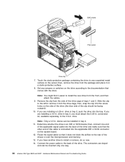
...you are installing a 5.25-in. drive in . If you are installing a 3.5-in bay 2, push the drive into the screw holes on the system board. 12. If you must attach the 5.25-in bay 4. 11. conversion kit, available separately, to install or remove, do so now. 14. drive...in . Touch the static-protective package containing the drive to the documentation that comes with the drive. then, connect one way. 34 xSeries 206 Type 8482 and 8487: Hardware Maintenance Manual and Troubleshooting Guide drive in bay 2, you have another drive to the 3.5-in . Connect the power ...
...you are installing a 5.25-in. drive in . If you are installing a 3.5-in bay 2, push the drive into the screw holes on the system board. 12. If you must attach the 5.25-in bay 4. 11. conversion kit, available separately, to install or remove, do so now. 14. drive...in . Touch the static-protective package containing the drive to the documentation that comes with the drive. then, connect one way. 34 xSeries 206 Type 8482 and 8487: Hardware Maintenance Manual and Troubleshooting Guide drive in bay 2, you have another drive to the 3.5-in . Connect the power ...
User Manual
Page 47
... drives in the hot-swap drive bays; v If the server has an optional RAID adapter, see the documentation that the drive is the printed circuit board behind the bay. The server hot-swap bays are connected to a hard disk drive backplane. v You do not have to turn off the server to...
... drives in the hot-swap drive bays; v If the server has an optional RAID adapter, see the documentation that the drive is the printed circuit board behind the bay. The server hot-swap bays are connected to a hard disk drive backplane. v You do not have to turn off the server to...
User Manual
Page 51
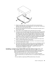
...the drive. Installing options 41 See "Power and signal cables for internal drives" on page 43 for additional information about cabling drives and "System-board internal connectors" on page 70 for cabling instructions. v You can be inserted only one end of the SCSI signal cable into the SCSI connector...bracket (see "Removing and installing the support bracket" on page 28), and replace the side cover (see "Replacing the side cover" on the system board. Connect one way. 15. Route the signal cable so that are keyed and can install two simple-swap SATA hard disk drives in bay 5, 6,...
...the drive. Installing options 41 See "Power and signal cables for internal drives" on page 43 for additional information about cabling drives and "System-board internal connectors" on page 70 for cabling instructions. v You can be inserted only one end of the SCSI signal cable into the SCSI connector...bracket (see "Removing and installing the support bracket" on page 28), and replace the side cover (see "Replacing the side cover" on the system board. Connect one way. 15. Route the signal cable so that are keyed and can install two simple-swap SATA hard disk drives in bay 5, 6,...

User Manual
Page 52
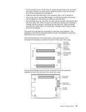
... in bay 2 or 4" on page 107. 2. Bay 1 Bay 2 Bay 3 Bay 4 Bay 5 Bay 6 Bay 7 Recess area Door hatch 42 xSeries 206 Type 8482 and 8487: Hardware Maintenance Manual and Troubleshooting Guide v Install simple-swap SATA hard disk drives in order to allow the door hatch to remove the... side cover. 4. Complete the following steps to the ServeRAID 7t S-ATA controller instead of the system board. Bay 4 is unlocked in ...
... in bay 2 or 4" on page 107. 2. Bay 1 Bay 2 Bay 3 Bay 4 Bay 5 Bay 6 Bay 7 Recess area Door hatch 42 xSeries 206 Type 8482 and 8487: Hardware Maintenance Manual and Troubleshooting Guide v Install simple-swap SATA hard disk drives in order to allow the door hatch to remove the... side cover. 4. Complete the following steps to the ServeRAID 7t S-ATA controller instead of the system board. Bay 4 is unlocked in ...
User Manual
Page 53
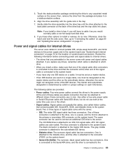
...The server uses cables to connect parallel IDE, simple-swap Serial ATA, and SCSI devices to the power supply and to the system board (see "System-board internal connectors" on the server; these connectors vary in the bay. 7. v Signal cables: Signal cables are typically flat cables, ...plastic connectors that one must be attached to any drives, remember which drive. The master and subordinate designation is attached to the system board. The following information before connecting power and signal cables to internal drives: v The drives that connect parallel IDE, Serial ATA, SCSI,...
...The server uses cables to connect parallel IDE, simple-swap Serial ATA, and SCSI devices to the power supply and to the system board (see "System-board internal connectors" on the server; these connectors vary in the bay. 7. v Signal cables: Signal cables are typically flat cables, ...plastic connectors that one must be attached to any drives, remember which drive. The master and subordinate designation is attached to the system board. The following information before connecting power and signal cables to internal drives: v The drives that connect parallel IDE, Serial ATA, SCSI,...
User Manual
Page 54
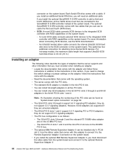
... slots 1 and 2 and the mini-PCI-X slot are on the system board. v The optional IBM Remote Supervisor Adapter II can be connected to the optional Remote Supervisor Adapter II. 44 xSeries 206 Type 8482 and 8487: Hardware Maintenance Manual and Troubleshooting Guide Each Serial ATA drive comes with... comes with the adapter. For more internal SCSI devices. Installing an adapter The following notes describe the types of the system board. This cable has four additional connectors for attaching more information about connecting SCSI devices, see the SCSI documentation. - connector on...
... slots 1 and 2 and the mini-PCI-X slot are on the system board. v The optional IBM Remote Supervisor Adapter II can be connected to the optional Remote Supervisor Adapter II. 44 xSeries 206 Type 8482 and 8487: Hardware Maintenance Manual and Troubleshooting Guide Each Serial ATA drive comes with... comes with the adapter. For more internal SCSI devices. Installing an adapter The following notes describe the types of the system board. This cable has four additional connectors for attaching more information about connecting SCSI devices, see the SCSI documentation. - connector on...

