User Guide
Page 5
The xSeries 206m server 1 Related documentation 1 Notices and statements in a rack 48 Chapter 3. Configuring the server 49 Using the Configuration/Setup Utility program 51 Starting the Configuration/Setup Utility program 51 Configuration/Setup Utility menu choices 51 Passwords 54 © Copyright IBM Corp. 2006...PCI-X expansion card 18 System-board LEDs 19 Installation guidelines 19 System reliability guidelines 20 Working inside the server with the power on 20 Handling static-sensitive devices 21 Removing the side cover 22 Removing the two-piece bezel 23 Installing a memory ...
The xSeries 206m server 1 Related documentation 1 Notices and statements in a rack 48 Chapter 3. Configuring the server 49 Using the Configuration/Setup Utility program 51 Starting the Configuration/Setup Utility program 51 Configuration/Setup Utility menu choices 51 Passwords 54 © Copyright IBM Corp. 2006...PCI-X expansion card 18 System-board LEDs 19 Installation guidelines 19 System reliability guidelines 20 Working inside the server with the power on 20 Handling static-sensitive devices 21 Removing the side cover 22 Removing the two-piece bezel 23 Installing a memory ...
User Guide
Page 9
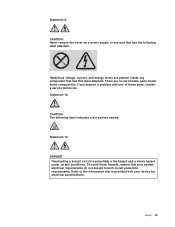
... procedures. v When possible, use one hand only to outlet. 5. Turn everything OFF. 2. Turn device ON. v Disconnect the attached power cords, telecommunications systems, networks, and modems before you open the device covers, unless instructed otherwise in the following table when installing, moving,... or opening covers on any equipment when there is hazardous. Attach power cords to connect or disconnect signal cables. Remove all power cords to a properly wired and grounded electrical outlet. To avoid a shock hazard: v Do not connect...
... procedures. v When possible, use one hand only to outlet. 5. Turn everything OFF. 2. Turn device ON. v Disconnect the attached power cords, telecommunications systems, networks, and modems before you open the device covers, unless instructed otherwise in the following table when installing, moving,... or opening covers on any equipment when there is hazardous. Attach power cords to connect or disconnect signal cables. Remove all power cords to a properly wired and grounded electrical outlet. To avoid a shock hazard: v Do not connect...
User Guide
Page 12
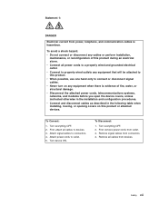
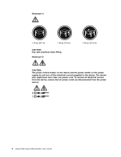
The device also might have more than one power cord. To remove all electrical current from the device, ensure that all power cords are disconnected from the power source. 2 1 x xSeries 206m Types 8485 and 8490: User's Guide Statement 5: ≥ 55 kg (121.2 lb) CAUTION: The power control button on the device and the power switch on the power supply do not turn off the electrical current supplied to the device. Statement 4: ≥ 18 kg (39.7 lb) ≥ 32 kg (70.5 lb) CAUTION: Use safe practices when lifting.
The device also might have more than one power cord. To remove all electrical current from the device, ensure that all power cords are disconnected from the power source. 2 1 x xSeries 206m Types 8485 and 8490: User's Guide Statement 5: ≥ 55 kg (121.2 lb) CAUTION: The power control button on the device and the power switch on the power supply do not turn off the electrical current supplied to the device. Statement 4: ≥ 18 kg (39.7 lb) ≥ 32 kg (70.5 lb) CAUTION: Use safe practices when lifting.
User Guide
Page 13
...: CAUTION: The following label attached. Statement 13: DANGER Overloading a branch circuit is provided with one of these components. Statement 8: CAUTION: Never remove the cover on a power supply or any component that has this label attached. If you suspect a problem with your system electrical requirements do not exceed branch circuit protection requirements...
...: CAUTION: The following label attached. Statement 13: DANGER Overloading a branch circuit is provided with one of these components. Statement 8: CAUTION: Never remove the cover on a power supply or any component that has this label attached. If you suspect a problem with your system electrical requirements do not exceed branch circuit protection requirements...
User Guide
Page 17
... voltage and frequency ranges automatically selected v Input voltage low range: - The declared sound-power levels indicate an upper limit, below which a large number of optional features installed and the power-management optional features in a given location might not apply. The xSeries 206m server 3 CD-ROM - Simple-swap bays with ISO 9296. Non-hot-swap...
... voltage and frequency ranges automatically selected v Input voltage low range: - The declared sound-power levels indicate an upper limit, below which a large number of optional features installed and the power-management optional features in a given location might not apply. The xSeries 206m server 3 CD-ROM - Simple-swap bays with ISO 9296. Non-hot-swap...
User Guide
Page 18
...CD, see http://www.ibm.com/servers/eserver/xseries/xarchitecture/ enterprise/index.html. This will overwrite the existing preload. With the hot-swap feature, you diagnose the problem. v High-performance graphics controller The server comes with the 4 xSeries 206m Types 8485 and 8490: User's ..., see "Configuring the Broadcom Gigabit Ethernet controller" on the IBM Director CD. The memory controller supports error correcting code (ECC) for the operating-system environment. What your Intel-processor-based server powerful, scalable, and reliable. If an environmental condition exceeds a ...
...CD, see http://www.ibm.com/servers/eserver/xseries/xarchitecture/ enterprise/index.html. This will overwrite the existing preload. With the hot-swap feature, you diagnose the problem. v High-performance graphics controller The server comes with the 4 xSeries 206m Types 8485 and 8490: User's ..., see "Configuring the Broadcom Gigabit Ethernet controller" on the IBM Director CD. The memory controller supports error correcting code (ECC) for the operating-system environment. What your Intel-processor-based server powerful, scalable, and reliable. If an environmental condition exceeds a ...
User Guide
Page 19
... also provides system monitoring, event recording, and dial-out alert capability. The xSeries 206m server 5 The server also has integrated RAID level-0 and level-1 support. ...and serviceability (RAS). Chapter 1. See the documentation that comes with your IBM marketing representative or authorized reseller. primary Ethernet connection, all Ethernet traffic that...year parts, 1-year labor limited warranty (Machine Type 8485) and 3-year parts, 3-year labor limited warranty (Machine Type 8490) v Advanced Configuration and Power Interface (ACPI) v Advanced Desktop Management Interface (DMI...
... also provides system monitoring, event recording, and dial-out alert capability. The xSeries 206m server 5 The server also has integrated RAID level-0 and level-1 support. ...and serviceability (RAS). Chapter 1. See the documentation that comes with your IBM marketing representative or authorized reseller. primary Ethernet connection, all Ethernet traffic that...year parts, 1-year labor limited warranty (Machine Type 8485) and 3-year parts, 3-year labor limited warranty (Machine Type 8490) v Advanced Configuration and Power Interface (ACPI) v Advanced Desktop Management Interface (DMI...

User Guide
Page 20
...-management industry standards. 6 xSeries 206m Types 8485 and 8490: User's Guide includes serial-number information and replacement part numbers, stored in nonvolatile memory, for easier remote maintenance v Wake on LAN® capability IBM Director With IBM Director, a network administrator ... at http://www.ibm.com/servers/eserver/xseries/ systems_management/sys_migration/ibmdiragent.html. This document is updated every 6 to the error log v Mini baseboard management controller (mini-BMC) (service processor) v Power management v Power-on a variety of platforms IBM Director provides a...
...-management industry standards. 6 xSeries 206m Types 8485 and 8490: User's Guide includes serial-number information and replacement part numbers, stored in nonvolatile memory, for easier remote maintenance v Wake on LAN® capability IBM Director With IBM Director, a network administrator ... at http://www.ibm.com/servers/eserver/xseries/ systems_management/sys_migration/ibmdiragent.html. This document is updated every 6 to the error log v Mini baseboard management controller (mini-BMC) (service processor) v Power management v Power-on a variety of platforms IBM Director provides a...
User Guide
Page 22
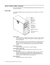
... CD-eject or DVD-eject button CD or DVD drive activity LED (Optional) Diskette-eject button (Optional) Diskette drive activity LED Power-on the IBM xSeries Documentation CD. USB connectors Connect USB devices to turn the server on the front of the server. Note: If this LED is..., and connectors on and off manually. System-error LED When this button to these connectors. 8 xSeries 206m Types 8485 and 8490: User's Guide Power-control button Press this amber LED is no electrical power in the Problem Determination and Service Guide on LED When this LED is off , it indicates that...
... CD-eject or DVD-eject button CD or DVD drive activity LED (Optional) Diskette-eject button (Optional) Diskette drive activity LED Power-on the IBM xSeries Documentation CD. USB connectors Connect USB devices to turn the server on the front of the server. Note: If this LED is..., and connectors on and off manually. System-error LED When this button to these connectors. 8 xSeries 206m Types 8485 and 8490: User's Guide Power-control button Press this amber LED is no electrical power in the Problem Determination and Service Guide on LED When this LED is off , it indicates that...
User Guide
Page 24
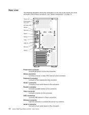
... a mouse or other PS/2 device to this connector. 10 xSeries 206m Types 8485 and 8490: User's Guide Keyboard connector Connect a PS/2 keyboard to this connector. Power cord Power supply error LED AC power LED Mouse Keyboard Serial 1 Parallel Video USB (2) Ethernet Serial 2 Power-cord connector Connect the power cord to this connector. USB connectors Connect USB devices to...
... a mouse or other PS/2 device to this connector. 10 xSeries 206m Types 8485 and 8490: User's Guide Keyboard connector Connect a PS/2 keyboard to this connector. Power cord Power supply error LED AC power LED Mouse Keyboard Serial 1 Parallel Video USB (2) Ethernet Serial 2 Power-cord connector Connect the power cord to this connector. USB connectors Connect USB devices to...
User Guide
Page 25
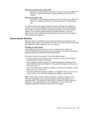
... the server, the server can also be turned on the server. v If an optional Remote Supervisor Adapter II is shut down; Chapter 1. The xSeries 206m server 11 Server power features When the server is connected to the operating system. If an optional Remote Supervisor Adapter II (systems-management adapter) is unavailable to an...
... the server, the server can also be turned on the server. v If an optional Remote Supervisor Adapter II is shut down; Chapter 1. The xSeries 206m server 11 Server power features When the server is connected to the operating system. If an optional Remote Supervisor Adapter II (systems-management adapter) is unavailable to an...
User Guide
Page 26
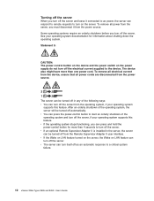
... as an automatic response to turn on LAN feature can turn off the server and leave it from the power source. v You can respond to remote requests to a critical system failure. 12 xSeries 206m Types 8485 and 8490: User's Guide v If the Wake on LAN feature turned on the server, the Wake on the...
... as an automatic response to turn on LAN feature can turn off the server and leave it from the power source. v You can respond to remote requests to a critical system failure. 12 xSeries 206m Types 8485 and 8490: User's Guide v If the Wake on LAN feature turned on the server, the Wake on the...
User Guide
Page 27
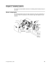
... for installing optional hardware devices in this document might differ slightly from your hardware. The illustrations in the server. System board Fan DIMM Power supply Heat sink Microprocessor Drive cage Mini-PCI-X adapter (SAS/SATA controller) Front adaptersupport bracket Cover PCI-X expansion card EMC shields Filler ... filler panel SATA hard disk drive (some models) SAS filler panel Hot-swap hard disk drive (some models) © Copyright IBM Corp. 2006 13 Server components The following illustration shows the major components in the server (depending on the server model).
... for installing optional hardware devices in this document might differ slightly from your hardware. The illustrations in the server. System board Fan DIMM Power supply Heat sink Microprocessor Drive cage Mini-PCI-X adapter (SAS/SATA controller) Front adaptersupport bracket Cover PCI-X expansion card EMC shields Filler ... filler panel SATA hard disk drive (some models) SAS filler panel Hot-swap hard disk drive (some models) © Copyright IBM Corp. 2006 13 Server components The following illustration shows the major components in the server (depending on the server model).
User Guide
Page 28
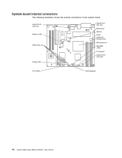
System-board internal connectors The following illustration shows the internal connectors on LAN SATA drives (4) Primary IDE System fan 1 (fan sink) Main power Battery Power (Optional) Diskette drive Microprocessor Mini-BMC JTAG Front panel System fan 2 (front fan) Front USB SAS backplane 14 xSeries 206m Types 8485 and 8490: User's Guide System fan 3 (rear fan) Wake on the system board.
System-board internal connectors The following illustration shows the internal connectors on LAN SATA drives (4) Primary IDE System fan 1 (fan sink) Main power Battery Power (Optional) Diskette drive Microprocessor Mini-BMC JTAG Front panel System fan 2 (front fan) Front USB SAS backplane 14 xSeries 206m Types 8485 and 8490: User's Guide System fan 3 (rear fan) Wake on the system board.
User Guide
Page 29
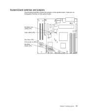
Installing options 15 There are no changeable switches on (JP8) Mini-BMC disable (JP7) Chapter 2. Mini-BMC force update (JP1) Clear CMOS (JP2) Boot block (JP6) Force power on the system board. System-board switches and jumpers The following illustration shows the jumpers on the system board.
Installing options 15 There are no changeable switches on (JP8) Mini-BMC disable (JP7) Chapter 2. Mini-BMC force update (JP1) Clear CMOS (JP2) Boot block (JP6) Force power on the system board. System-board switches and jumpers The following illustration shows the jumpers on the system board.
User Guide
Page 33
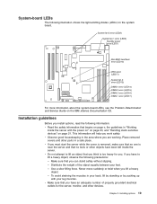
... Before you are working. Never move suddenly or twist when you can stand safely without slipping. - System fan 3 error (LED2) System fan 1 error (LED3) Standby power good (LED1) Mini-BMC heartbeat error (LED10) VRD good (LED11) System fan 2 error (LED13) DIMM 4 error (LED14) DIMM 3 error (LED15) DIMM 2 ...Problem Determination and Service Guide on the system board. System-board LEDs The following illustration shows the light-emitting diodes (LEDs) on the IBM xSeries Documentation CD. Make sure that begins on page 21. v Make sure that you have to lift an object that you think is ...
... Before you are working. Never move suddenly or twist when you can stand safely without slipping. - System fan 3 error (LED2) System fan 1 error (LED3) Standby power good (LED1) Mini-BMC heartbeat error (LED10) VRD good (LED11) System fan 2 error (LED13) DIMM 4 error (LED14) DIMM 3 error (LED15) DIMM 2 ...Problem Determination and Service Guide on the system board. System-board LEDs The following illustration shows the light-emitting diodes (LEDs) on the IBM xSeries Documentation CD. Make sure that begins on page 21. v Make sure that you have to lift an object that you think is ...
User Guide
Page 34
..., which could result in the server, open space around the server to allow the server cooling system to work inside the server. 20 xSeries 206m Types 8485 and 8490: User's Guide v You have to disk drives. The server supports hot-plug, hot-add, and hot-swap devices and ...or hot-plug Universal Serial Bus (USB) devices. Operating the server for the server, see http://www.ibm.com/servers/ eserver/serverproven/compat/us/. v Avoid wearing loose-fitting clothing on and the cover is powered-on the server. v For a list of the drive bays has a drive or a filler panel ...
..., which could result in the server, open space around the server to allow the server cooling system to work inside the server. 20 xSeries 206m Types 8485 and 8490: User's Guide v You have to disk drives. The server supports hot-plug, hot-add, and hot-swap devices and ...or hot-plug Universal Serial Bus (USB) devices. Operating the server for the server, see http://www.ibm.com/servers/ eserver/serverproven/compat/us/. v Avoid wearing loose-fitting clothing on and the cover is powered-on the server. v For a list of the drive bays has a drive or a filler panel ...
User Guide
Page 35
... from your movement. Heating reduces indoor humidity and increases static electricity. v Do not allow your necktie or scarf to hang inside the server with the power on. Handling static-sensitive devices Attention: Static electricity can handle and damage it to an unpainted metal surface on a metal surface. v The use an electrostatic...
... from your movement. Heating reduces indoor humidity and increases static electricity. v Do not allow your necktie or scarf to hang inside the server with the power on. Handling static-sensitive devices Attention: Static electricity can handle and damage it to an unpainted metal surface on a metal surface. v The use an electrostatic...
User Guide
Page 36
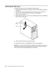
... the side cover; Lift the side cover off the server and all power cords and external cables. 3. Operating the server for extended periods of time (more than 30 minutes) with the cover removed might damage server components. 22 xSeries 206m Types 8485 and 8490: User's Guide Removing the side cover To remove the server...
... the side cover; Lift the side cover off the server and all power cords and external cables. 3. Operating the server for extended periods of time (more than 30 minutes) with the cover removed might damage server components. 22 xSeries 206m Types 8485 and 8490: User's Guide Removing the side cover To remove the server...

User Guide
Page 40
... potential problem, always use an electrostatic-discharge wrist strap or other grounding system when working inside the server with the power on page 22). 26 xSeries 206m Types 8485 and 8490: User's Guide Remove the side cover (see "Removing the side cover" on . Read the safety ...: Static electricity that begins on page v and "Installation guidelines" on might cause the server to internal server components when the server is powered-on page 19. 2. To install a DIMM, complete the following illustration shows the dual inline memory module (DIMM) connectors and corresponding LEDs...
... potential problem, always use an electrostatic-discharge wrist strap or other grounding system when working inside the server with the power on page 22). 26 xSeries 206m Types 8485 and 8490: User's Guide Remove the side cover (see "Removing the side cover" on . Read the safety ...: Static electricity that begins on page v and "Installation guidelines" on might cause the server to internal server components when the server is powered-on page 19. 2. To install a DIMM, complete the following illustration shows the dual inline memory module (DIMM) connectors and corresponding LEDs...


