
Service Manual
Page 8
Table of Contents Removal and Installation 8-1 Introduction 8-2 Safety Precautions 8-2 Electrostatic Discharge (ESD) Precautions 8-3 Required Tools 8-3 Screw Types 8-4 Left Hand Cover 8-5 Right Hand Cover 8-7 Front Panel 8-9 Window and Top Cover 8-10 Media Deflectors 8-11 Left End Roll-Feed 8-13 Right End Roll-Feed 8-15 Back Platen 8-17 Media Sensor 8-19 Formatter 8-20 ... Service Station Holder 8-57 Interconnect Cable 8-59 Ink Supply Tubes 8-60 Vacuum Fan 8-64 Pinch-Arm 8-66 Pinch-Arm Mechanism 8-67 Pinch-Arm Lever 8-69 6 HP DesignJets 500 and 800 Series Printers Service Manual
Table of Contents Removal and Installation 8-1 Introduction 8-2 Safety Precautions 8-2 Electrostatic Discharge (ESD) Precautions 8-3 Required Tools 8-3 Screw Types 8-4 Left Hand Cover 8-5 Right Hand Cover 8-7 Front Panel 8-9 Window and Top Cover 8-10 Media Deflectors 8-11 Left End Roll-Feed 8-13 Right End Roll-Feed 8-15 Back Platen 8-17 Media Sensor 8-19 Formatter 8-20 ... Service Station Holder 8-57 Interconnect Cable 8-59 Ink Supply Tubes 8-60 Vacuum Fan 8-64 Pinch-Arm 8-66 Pinch-Arm Mechanism 8-67 Pinch-Arm Lever 8-69 6 HP DesignJets 500 and 800 Series Printers Service Manual

Service Manual
Page 15
...: n Check that the Vacuum Fan is a problem with the Vacuum Fan, try the following: 1 With the Printer ON, open the Window of the Printer and place a sheet of HP High Gloss Photo Paper (must be D-Size), aligned with the blue lines on the Media. In this would be done via the... if there really is installed correctly. If the Vacuum Fan does not hold the sheet in place properly causing: n Ink Smearing on the Center Platen. HP DesignJets 500 and 800 Series Printers Service Manual 1-5 n Check that the holes in place, but couldn't correctly load it correctly, then the Vacuum Fan...
...: n Check that the Vacuum Fan is a problem with the Vacuum Fan, try the following: 1 With the Printer ON, open the Window of the Printer and place a sheet of HP High Gloss Photo Paper (must be D-Size), aligned with the blue lines on the Media. In this would be done via the... if there really is installed correctly. If the Vacuum Fan does not hold the sheet in place properly causing: n Ink Smearing on the Center Platen. HP DesignJets 500 and 800 Series Printers Service Manual 1-5 n Check that the holes in place, but couldn't correctly load it correctly, then the Vacuum Fan...

Service Manual
Page 18
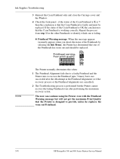
...ink the Printer will proceed to continue Menu Back Enter Check for ink Open the Carriage Cover and check if there is ink inside printhead windows 3. Press ENTER to the Printhead replacement process. ALL with some ink NOT all with ink Menu Back Enter If there is ink inside ...2. On the Front Panel you will see the following message on the source of the problem: 1-8 HP DesignJets 500 and 800 Series Printers Service Manual Open window to check SETUP printheads Open the Window and you will see the following question and you will need to prepare ink system. Check if there...
...ink the Printer will proceed to continue Menu Back Enter Check for ink Open the Carriage Cover and check if there is ink inside printhead windows 3. Press ENTER to the Printhead replacement process. ALL with some ink NOT all with ink Menu Back Enter If there is ink inside ...2. On the Front Panel you will see the following message on the source of the problem: 1-8 HP DesignJets 500 and 800 Series Printers Service Manual Open window to check SETUP printheads Open the Window and you will see the following question and you will need to prepare ink system. Check if there...
Service Manual
Page 54
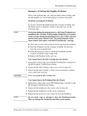
... the maximum recovery action. n Printhead Warning message. Ink Supplies Troubleshooting 3 Reinsert the Cyan Printhead only and close the Carriage cover and the Window. 4 Check the front panel - NOTE The Printer normally determines this message appears (normally appears when you check the status of the Printheads ...1 The Printhead Alignment fails due to a faulty Printhead and the Printer tries to provide, unless he replaces the worn out Printhead. 3-8 HP DesignJets 500 and 800 Series Printers Service Manual then the conclusion is that one is faulty and must be replaced.
... the maximum recovery action. n Printhead Warning message. Ink Supplies Troubleshooting 3 Reinsert the Cyan Printhead only and close the Carriage cover and the Window. 4 Check the front panel - NOTE The Printer normally determines this message appears (normally appears when you check the status of the Printheads ...1 The Printhead Alignment fails due to a faulty Printhead and the Printer tries to provide, unless he replaces the worn out Printhead. 3-8 HP DesignJets 500 and 800 Series Printers Service Manual then the conclusion is that one is faulty and must be replaced.
Service Manual
Page 69
...and 800 Series Printers Service Manual 3-23 Problems reseating the Printhead If you have the correct HP Printhead that is suitable for the HP DesignJet 500/800 Series Printer. 2 Ensure that the printhead is the correct color for that...(displays a faulty or missing icon), try the following steps. n Check that you have the correct HP Ink Cartridge that is suitable for the HP DesignJet 500/800 Series Printer. 2 Ensure that the Ink Cartridge is the correct color for that slot... be rejected and the front panel will show the "Normal printheads found Open window and replace with a new one.
...and 800 Series Printers Service Manual 3-23 Problems reseating the Printhead If you have the correct HP Printhead that is suitable for the HP DesignJet 500/800 Series Printer. 2 Ensure that the printhead is the correct color for that...(displays a faulty or missing icon), try the following steps. n Check that you have the correct HP Ink Cartridge that is suitable for the HP DesignJet 500/800 Series Printer. 2 Ensure that the Ink Cartridge is the correct color for that slot... be rejected and the front panel will show the "Normal printheads found Open window and replace with a new one.
Service Manual
Page 82
...displayed: Paper Advance test System error 81:11 Paper-axis shutdown WARNING In this case, to resolve the problem, try the following: 1 Open the Window and check for any visible obstacles that while performing this test, a Paper-Axis shutdown occurs, in which component failed. 5 If the Drive Roller...Roller service utility ⇒ Page 4-21. Please wait 6 Once the test is possible that could be restricting the movement of the PWM 4-12 HP DesignJets 500 and 800 Series Printers Service Manual Only replace one component at a time and try cleaning the Drive Roller Gears. 3 Replace the ...
...displayed: Paper Advance test System error 81:11 Paper-axis shutdown WARNING In this case, to resolve the problem, try the following: 1 Open the Window and check for any visible obstacles that while performing this test, a Paper-Axis shutdown occurs, in which component failed. 5 If the Drive Roller...Roller service utility ⇒ Page 4-21. Please wait 6 Once the test is possible that could be restricting the movement of the PWM 4-12 HP DesignJets 500 and 800 Series Printers Service Manual Only replace one component at a time and try cleaning the Drive Roller Gears. 3 Replace the ...
Service Manual
Page 93
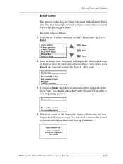
... the Printer will need to force the priming procedure). Prime tubes Press ENTER to force tube priming at next power up Printheads. Open window and remove normal printheads to "Prime tubes" and press Enter. You will initialize and then display the following message on machine to start... and replace them with Start-up . Prime the tubes as follows: 1 In the Service Utilities submenu, scroll to prepare ink system HP DesignJets 500 and 800 Series Printers Service Manual 4-23 Service utilities Change ink tubes Unlock Carriage Turn Drive Roller Prime tubes EEROM Setup Menu...
... the Printer will need to force the priming procedure). Prime tubes Press ENTER to force tube priming at next power up Printheads. Open window and remove normal printheads to "Prime tubes" and press Enter. You will initialize and then display the following message on machine to start... and replace them with Start-up . Prime the tubes as follows: 1 In the Service Utilities submenu, scroll to prepare ink system HP DesignJets 500 and 800 Series Printers Service Manual 4-23 Service utilities Change ink tubes Unlock Carriage Turn Drive Roller Prime tubes EEROM Setup Menu...

Service Manual
Page 106
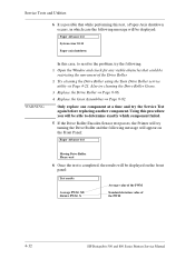
n Clean the Line Sensor and try the following message will appear on the front panel: Calibration error. Service Calibrations If the calibration fails, then the following : n Make sure that the Window is closed when you DO NOT use transparent media when performing the Color Calibration. n Make sure that you perform the Color Calibration. 5-8 HP DesignJets 500 and 800 Series Printers Service Manual Press ENTER to continue Menu Back Enter In this case, to resolve the problem, try the Calibration again.
n Clean the Line Sensor and try the following message will appear on the front panel: Calibration error. Service Calibrations If the calibration fails, then the following : n Make sure that the Window is closed when you DO NOT use transparent media when performing the Color Calibration. n Make sure that you perform the Color Calibration. 5-8 HP DesignJets 500 and 800 Series Printers Service Manual Press ENTER to continue Menu Back Enter In this case, to resolve the problem, try the Calibration again.
Service Manual
Page 120
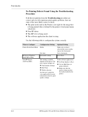
... printer's front-panel menu selections). The settings available depend on the driver. What to Automatic. Set to Configure Printer Front-Panel Menu HP driver (Windows, AutoCAD or Mac) Non-HP drivers (Software RIPs) Configuration Setting Media Dry time Print mode setting Optimal Setting Make sure you still experience print quality problems, here are... the Troubleshooting Procedure If all the test patterns from the Troubleshooting procedure are correct and you have selected the correct media type in the printer. 6-8 HP DesignJets 500 and 800 Series Printers Service Manual n Non...
... printer's front-panel menu selections). The settings available depend on the driver. What to Automatic. Set to Configure Printer Front-Panel Menu HP driver (Windows, AutoCAD or Mac) Non-HP drivers (Software RIPs) Configuration Setting Media Dry time Print mode setting Optimal Setting Make sure you still experience print quality problems, here are... the Troubleshooting Procedure If all the test patterns from the Troubleshooting procedure are correct and you have selected the correct media type in the printer. 6-8 HP DesignJets 500 and 800 Series Printers Service Manual n Non...

Service Manual
Page 167
Removal and Installation 8 Screw Types 8-4 Left Hand Cover 8-5 Right Hand Cover 8-7 Front Panel 8-9 Window and Top Cover 8-10 Media Deflectors 8-11 Left End Roll-Feed 8-13 Right End Roll-Feed 8-15 Back Platen 8-17 Media Sensor 8-19 Formatter 8-20 ... Fork Idler, Tensioner and Idler Pulley 8-74 Encoder Strip 8-76 Carriage Assembly (Including Belt) 8-78 Paper-Axis Motor 8-84 Drive Roller 8-86 Gear Assemblies 8-92 HP DesignJets 500 and 800 Series Printers Service Manual 8-1
Removal and Installation 8 Screw Types 8-4 Left Hand Cover 8-5 Right Hand Cover 8-7 Front Panel 8-9 Window and Top Cover 8-10 Media Deflectors 8-11 Left End Roll-Feed 8-13 Right End Roll-Feed 8-15 Back Platen 8-17 Media Sensor 8-19 Formatter 8-20 ... Fork Idler, Tensioner and Idler Pulley 8-74 Encoder Strip 8-76 Carriage Assembly (Including Belt) 8-78 Paper-Axis Motor 8-84 Drive Roller 8-86 Gear Assemblies 8-92 HP DesignJets 500 and 800 Series Printers Service Manual 8-1
Service Manual
Page 172
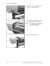
Remove 1 T-20 screw (Type F) from the side-plate. Open the Window and remove 1 T-20 screw (Type F) from the front of Left Hand Cover. 5. NOTE Be careful not to drop the screw into the Printer. 6. Remove the Left Hand Cover. 8-6 HP DesignJets 500 and 800 Series Printers Service Manual Removal and Installation 4.
Remove 1 T-20 screw (Type F) from the side-plate. Open the Window and remove 1 T-20 screw (Type F) from the front of Left Hand Cover. 5. NOTE Be careful not to drop the screw into the Printer. 6. Remove the Left Hand Cover. 8-6 HP DesignJets 500 and 800 Series Printers Service Manual Removal and Installation 4.
Service Manual
Page 174
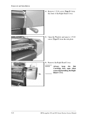
Open the Window and remove 1 T-20 screw (Type F) from the front of the Right Hand Cover. 5. Remove the Right Hand Cover. Remove 1 T-20 screw (Type F) from the side plate. 6. Removal and Installation 4. NOTE Always keep the Ink Cartridge door open when removing/installing the Right Hand Cover. 8-8 HP DesignJets 500 and 800 Series Printers Service Manual
Open the Window and remove 1 T-20 screw (Type F) from the front of the Right Hand Cover. 5. Remove the Right Hand Cover. Remove 1 T-20 screw (Type F) from the side plate. 6. Removal and Installation 4. NOTE Always keep the Ink Cartridge door open when removing/installing the Right Hand Cover. 8-8 HP DesignJets 500 and 800 Series Printers Service Manual
Service Manual
Page 176
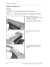
Removal and Installation Window and Top Cover Removal WARNING Switch off the printer and remove the power cord. Remove the following screws (Type A) from Printer. 8-10 HP DesignJets 500 and 800 Series Printers Service Manual NOTE Refer to the Printer: n 2 T-20 screws for the 24" model. Lift up complete assembly (Window and Top Cover) and remove from the rear that attach the Top Cover to the table on Page 8-4 for the 42" model. 2. Raise Window and unclip at both ends. 3. n 3 T-20 screws for information on screw types. 1.
Removal and Installation Window and Top Cover Removal WARNING Switch off the printer and remove the power cord. Remove the following screws (Type A) from Printer. 8-10 HP DesignJets 500 and 800 Series Printers Service Manual NOTE Refer to the Printer: n 2 T-20 screws for the 24" model. Lift up complete assembly (Window and Top Cover) and remove from the rear that attach the Top Cover to the table on Page 8-4 for the 42" model. 2. Raise Window and unclip at both ends. 3. n 3 T-20 screws for information on screw types. 1.
Service Manual
Page 198
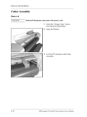
Lift Tab UP and pull out the Cutter Assembly. 8-32 HP DesignJets 500 and 800 Series Printers Service Manual Removal and Installation Cutter Assembly Removal WARNING Switch off the printer and remove the power cord. 1. Select the "Change Cutter" option from the Front Panel Menu. 2. Open the Window. 1 3 2 3.
Lift Tab UP and pull out the Cutter Assembly. 8-32 HP DesignJets 500 and 800 Series Printers Service Manual Removal and Installation Cutter Assembly Removal WARNING Switch off the printer and remove the power cord. 1. Select the "Change Cutter" option from the Front Panel Menu. 2. Open the Window. 1 3 2 3.
Service Manual
Page 206
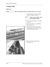
NOTE Switch off the Printer after performing this Utility. 2. Release the latch and lift up the Carriage Cover. 8-40 HP DesignJets 500 and 800 Series Printers Service Manual Removal and Installation Trailing Cable Removal NOTE Refer to Page 8-5. 3. Perform the Service Utility "Unlock Carriage" - Refer to the table on Page 8-4 for information on screw types. 1. Remove the Left Hand Cover - Remove the Top Cover and Window Refer to remove the Tubes Assembly from the Carriage. 5. Manually move the carriage to the correct position to Page 8-10. 4. Refer to Page 4-22.
NOTE Switch off the Printer after performing this Utility. 2. Release the latch and lift up the Carriage Cover. 8-40 HP DesignJets 500 and 800 Series Printers Service Manual Removal and Installation Trailing Cable Removal NOTE Refer to Page 8-5. 3. Perform the Service Utility "Unlock Carriage" - Refer to the table on Page 8-4 for information on screw types. 1. Remove the Left Hand Cover - Remove the Top Cover and Window Refer to remove the Tubes Assembly from the Carriage. 5. Manually move the carriage to the correct position to Page 8-10. 4. Refer to Page 4-22.

Service Manual
Page 226
Release the latch and lift up the Carriage Cover. 4. Remove all the Printheads. 8-60 HP DesignJets 500 and 800 Series Printers Service Manual Removal and Installation Ink Supply Tubes Removal 1. Perform the Service Utility "Change Ink Tubes" - Open the Window and locate the Carriage Assembly. 3. Refer to Page 4-25. 2.
Release the latch and lift up the Carriage Cover. 4. Remove all the Printheads. 8-60 HP DesignJets 500 and 800 Series Printers Service Manual Removal and Installation Ink Supply Tubes Removal 1. Perform the Service Utility "Change Ink Tubes" - Open the Window and locate the Carriage Assembly. 3. Refer to Page 4-25. 2.

Service Manual
Page 228
Unclip the Tubes from the Carriage and lift up. 8-62 HP DesignJets 500 and 800 Series Printers Service Manual Unclip 10. Remove the Top Cover and Window Refer to the Carriage. Removal and Installation 8. Loosen 1 T-8 screw that secures the Tubes to Page 8-10. 9.
Unclip the Tubes from the Carriage and lift up. 8-62 HP DesignJets 500 and 800 Series Printers Service Manual Unclip 10. Remove the Top Cover and Window Refer to the Carriage. Removal and Installation 8. Loosen 1 T-8 screw that secures the Tubes to Page 8-10. 9.

Service Manual
Page 244
... move the carriage to the correct position to Page 8-5. 3. Perform the Service Utility "Unlock Carriage" - Refer to remove the Tubes Assembly from the Carriage. 8-78 HP DesignJets 500 and 800 Series Printers Service Manual Refer to Page 8-9. 6. Remove the Right Hand Cover - Remove the Front Panel Assembly Refer to Page 8-52... to Page 8-57. 10. Removal and Installation Carriage Assembly (Including Belt) Removal 1. Refer to Page 8-10. 5. Remove the Encoder Strip - Remove the Top Cover and Window Refer to Page 4-22.
... move the carriage to the correct position to Page 8-5. 3. Perform the Service Utility "Unlock Carriage" - Refer to remove the Tubes Assembly from the Carriage. 8-78 HP DesignJets 500 and 800 Series Printers Service Manual Refer to Page 8-9. 6. Remove the Right Hand Cover - Remove the Front Panel Assembly Refer to Page 8-52... to Page 8-57. 10. Removal and Installation Carriage Assembly (Including Belt) Removal 1. Refer to Page 8-10. 5. Remove the Encoder Strip - Remove the Top Cover and Window Refer to Page 4-22.
Service Manual
Page 252
... to Page 8-10. 7. Remove the Top Cover and Window Refer to Page 8-7. 4. Remove the Media Sensor - Refer to Page 8-38. 14. Refer to Page 8-19. 10. Refer to Page 8-32. 12. Remove the Left and Right Trims. 5. Refer to Page 8-55. 8-86 HP DesignJets 500 and 800 Series Printers Service Manual Remove...
... to Page 8-10. 7. Remove the Top Cover and Window Refer to Page 8-7. 4. Remove the Media Sensor - Refer to Page 8-38. 14. Refer to Page 8-19. 10. Refer to Page 8-32. 12. Remove the Left and Right Trims. 5. Refer to Page 8-55. 8-86 HP DesignJets 500 and 800 Series Printers Service Manual Remove...

Service Manual
Page 258
... the Drive Roller Encoder Sensor - Remove the Left Hand Cover - Refer to Page 8-7. 4. Remove the Media Sensor - Refer to Page 8-9. 6. Remove the Top Cover and Window Refer to Page 8-36. 13. Remove the Spittoon - Remove the Cutter Guide Bracket Refer to Page 8-10. 7. Refer to Page 8-84. 8-92... HP DesignJets 500 and 800 Series Printers Service Manual Remove the Cutter Guide - Refer to Page 8-38. 14. Refer to Page 8-48. 15. Remove the Ink ...
... the Drive Roller Encoder Sensor - Remove the Left Hand Cover - Refer to Page 8-7. 4. Remove the Media Sensor - Refer to Page 8-9. 6. Remove the Top Cover and Window Refer to Page 8-36. 13. Remove the Spittoon - Remove the Cutter Guide Bracket Refer to Page 8-10. 7. Refer to Page 8-84. 8-92... HP DesignJets 500 and 800 Series Printers Service Manual Remove the Cutter Guide - Refer to Page 8-38. 14. Refer to Page 8-48. 15. Remove the Ink ...


