Manual/User Guide
Page 37
...or crosstalk of the signal lines (AT bus) between the HA and the disk drive should be contacted with the spindle motor. No need to the ATA-5 interface. The disk drive is an abbreviation of address decoder, driver, and receiver. Thus, it the cause of the signal lines including the HA and... cable does not exceed the ATA-5 standard, and the cable length between the HA and the disk drive may be a great cause of ...
...or crosstalk of the signal lines (AT bus) between the HA and the disk drive should be contacted with the spindle motor. No need to the ATA-5 interface. The disk drive is an abbreviation of address decoder, driver, and receiver. Thus, it the cause of the signal lines including the HA and... cable does not exceed the ATA-5 standard, and the cable length between the HA and the disk drive may be a great cause of ...

Manual/User Guide
Page 46
...place ESD mat on it. Do not stack when carrying. HDD is occasionally damaged by the impact of the driver. (2) Please observe the tightening torque of a low impact when you use the driver of the screw strictly. M3 0.49 N·m (5 Kg·cm) - Installation (1) Please use an ...electric driver. Do not hit HDD each other. Recommended equipments ESD Shock Contents Wrist strap ESD mat Low shock driver Model JX-1200-3056-8 SKY-8A (Color Seiden Mat) SS-6500 Maker SUMITOMO 3M Achilles HIOS ...
...place ESD mat on it. Do not stack when carrying. HDD is occasionally damaged by the impact of the driver. (2) Please observe the tightening torque of a low impact when you use the driver of the screw strictly. M3 0.49 N·m (5 Kg·cm) - Installation (1) Please use an ...electric driver. Do not hit HDD each other. Recommended equipments ESD Shock Contents Wrist strap ESD mat Low shock driver Model JX-1200-3056-8 SKY-8A (Color Seiden Mat) SS-6500 Maker SUMITOMO 3M Achilles HIOS ...

Manual/User Guide
Page 56
The servo information is the read demodulation circuit using the servo information recorded on the media surface. (3) Spindle motor driver circuit The circuit measures the interval of a PHASE signal generated by a MPU and then reconverted to an analog signal for... and read output from the head. Theory of Device Operation 4.3 Circuit Configuration Figure 4.2 shows the power supply configuration of the disk drive, and Figure 4.3 shows the disk drive circuit configuration. (1) Read/write circuit The read/write circuit consists of the voice coil motor are listed below. • Data buffer...
The servo information is the read demodulation circuit using the servo information recorded on the media surface. (3) Spindle motor driver circuit The circuit measures the interval of a PHASE signal generated by a MPU and then reconverted to an analog signal for... and read output from the head. Theory of Device Operation 4.3 Circuit Configuration Figure 4.2 shows the power supply configuration of the disk drive, and Figure 4.3 shows the disk drive circuit configuration. (1) Read/write circuit The read/write circuit consists of the voice coil motor are listed below. • Data buffer...
Manual/User Guide
Page 67
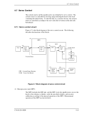
... capture MPU DSP unit Position Sense SVC (3) DAC (4) Power Amp VCM current (7) CSR VCM CSR: Current Sense Resister VCM: Voice Coil Motor (5) Spindle motor control (6) Driver Spindle motor Figure 4.7 Block diagram of the servo control circuit. 4.7 Servo Control 4.7 Servo Control The actuator motor and the spindle motor are shown below. To...
... capture MPU DSP unit Position Sense SVC (3) DAC (4) Power Amp VCM current (7) CSR VCM CSR: Current Sense Resister VCM: Voice Coil Motor (5) Spindle motor control (6) Driver Spindle motor Figure 4.7 Block diagram of the servo control circuit. 4.7 Servo Control 4.7 Servo Control The actuator motor and the spindle motor are shown below. To...
Manual/User Guide
Page 69
... Power amplifier The power amplifier feeds currents, corresponding to the DAC output signal voltage to the differentiation (aberration). (6) Driver circuit The driver circuit is in the servo burst capture circuit. At that indicate the head position from the servo data on the ...motor by the interrupt generated periodically, compares with A-B and C-D processed. (3) D/A converter (DAC) The D/A converter (DAC) converts the VCM drive current value (digital value) calculated by Fourierdemodulator in hold mode. C141-E120-02EN 4-17 4.7 Servo Control (2) Servo burst capture circuit The ...
... Power amplifier The power amplifier feeds currents, corresponding to the DAC output signal voltage to the differentiation (aberration). (6) Driver circuit The driver circuit is in the servo burst capture circuit. At that indicate the head position from the servo data on the ...motor by the interrupt generated periodically, compares with A-B and C-D processed. (3) D/A converter (DAC) The D/A converter (DAC) converts the VCM drive current value (digital value) calculated by Fourierdemodulator in hold mode. C141-E120-02EN 4-17 4.7 Servo Control (2) Servo burst capture circuit The ...
Manual/User Guide
Page 74
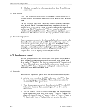
... and the 3phase full/half-wave analog current control circuit is used as the spindle motor driver (called SVC hereafter). The charged amount defines the current that , repeating this order). 4-... the SVC to the disk. These are three modes for each sampling time, the VCM drive current is determined by filtering the position difference between the target position and the position clarified ... the motor in the following sequence: a) After the power is turned on the MPU manufactured by Fujitsu. The MPU feeds the VCM current via the D/A converter and power amplifier to the motor start...
... and the 3phase full/half-wave analog current control circuit is used as the spindle motor driver (called SVC hereafter). The charged amount defines the current that , repeating this order). 4-... the SVC to the disk. These are three modes for each sampling time, the VCM drive current is determined by filtering the position difference between the target position and the position clarified ... the motor in the following sequence: a) After the power is turned on the MPU manufactured by Fujitsu. The MPU feeds the VCM current via the D/A converter and power amplifier to the motor start...

Manual/User Guide
Page 191
...10 Maximum time allowed for output drivers to release (from asserted or negated) tZAH 20 20 20 20 20 20 Minimum delay time required for output tZAD 0 0 0 0 0 0 Drivers to assert or negate (from released) tENV 20 70 20 70 20 70 20 55 20 55 20 50 Envelope time (from STROBE ...-to-pause time (that recipient shall wait to pause after negating DMARDY-) tIORDYZ 20 20 20 20 20 20 Maximum time before releasing IORDY tZIORDY 0 0 0 0 0 0 Minimum time before driving IORDY (*4) tACK 20 20 20 20 20 20 Setup and hold (tDH, tCH) times in ns) MIN MAX MIN MAX ...
...10 Maximum time allowed for output drivers to release (from asserted or negated) tZAH 20 20 20 20 20 20 Minimum delay time required for output tZAD 0 0 0 0 0 0 Drivers to assert or negate (from released) tENV 20 70 20 70 20 70 20 55 20 55 20 50 Envelope time (from STROBE ...-to-pause time (that recipient shall wait to pause after negating DMARDY-) tIORDYZ 20 20 20 20 20 20 Maximum time before releasing IORDY tZIORDY 0 0 0 0 0 0 Minimum time before driving IORDY (*4) tACK 20 20 20 20 20 20 Setup and hold (tDH, tCH) times in ns) MIN MAX MIN MAX ...
Manual/User Guide
Page 225
... standard collectively refers to the parameters defined by the host, which can handle the standard parameters of the drive do not always correspond to protect these drivers. Data block A data block is the first drive that can operate in command registers. To make full use of sectors per track in spindle motor, actuator...
... standard collectively refers to the parameters defined by the host, which can handle the standard parameters of the drive do not always correspond to protect these drivers. Data block A data block is the first drive that can operate in command registers. To make full use of sectors per track in spindle motor, actuator...


