
Manual/User Guide
Page 16
... in burst 5-125 5.6.4 Power-on and reset 5-126 CHAPTER 6 Operations 6-1 6.1 Device Response to the Reset 6-2 6.1.1 Response to power-on 6-2 6.1.2 Response to hardware reset 6-3 6.1.3 Response to software reset 6-5 6.1.4 Response to diagnostic command 6-6 xii C141-E120-02EN
... in burst 5-125 5.6.4 Power-on and reset 5-126 CHAPTER 6 Operations 6-1 6.1 Device Response to the Reset 6-2 6.1.1 Response to power-on 6-2 6.1.2 Response to hardware reset 6-3 6.1.3 Response to software reset 6-5 6.1.4 Response to diagnostic command 6-6 xii C141-E120-02EN
Manual/User Guide
Page 19
...18 Device pausing an Ultra DMA data out burst 5-123 Figure 5.19 Host terminating an Ultra DMA data out burst 5-124 Figure 5.20 Device terminating an Ultra DMA data out burst 5-125 Figure 5.21 Power-on Reset Timing 5-126 Figure 6.1 Response to power-on 6-3... Figure 6.2 Response to hardware reset 6-4 Figure 6.3 Response to software reset 6-5 Figure 6.4 Response to diagnostic command 6-6 Figure 6.5 Sector slip processing 6-10 Figure 6.6 Alternate cylinder assignment 6-11 Figure 6.7 Data buffer configuration 6-12...
...18 Device pausing an Ultra DMA data out burst 5-123 Figure 5.19 Host terminating an Ultra DMA data out burst 5-124 Figure 5.20 Device terminating an Ultra DMA data out burst 5-125 Figure 5.21 Power-on Reset Timing 5-126 Figure 6.1 Response to power-on 6-3... Figure 6.2 Response to hardware reset 6-4 Figure 6.3 Response to software reset 6-5 Figure 6.4 Response to diagnostic command 6-6 Figure 6.5 Sector slip processing 6-10 Figure 6.6 Alternate cylinder assignment 6-11 Figure 6.7 Data buffer configuration 6-12...

Manual/User Guide
Page 89
... Bit 5 Bit 4 Bit 3 Bit 2 Bit 1 Bit 0 BSY DRDY DF DSC DRQ 0 0 ERR (2) Device Control register (X'3F6') The Device Control register contains device interrupt and software reset. Bit 7 Bit 6 Bit 5 Bit 4 Bit 3 Bit 2 Bit 1 Bit 0 X X X X X SRST nIEN 0 - handshake. - The device can accept the ...block registers (1) Alternate Status register (X'3F6') The Alternate Status register contains the same information as the Status register of hardware or software reset. The only difference from the device to execute the DASP- The slave device is selected, an interruption (INTRQ signal) ...
... Bit 5 Bit 4 Bit 3 Bit 2 Bit 1 Bit 0 BSY DRDY DF DSC DRQ 0 0 ERR (2) Device Control register (X'3F6') The Device Control register contains device interrupt and software reset. Bit 7 Bit 6 Bit 5 Bit 4 Bit 3 Bit 2 Bit 1 Bit 0 X X X X X SRST nIEN 0 - handshake. - The device can accept the ...block registers (1) Alternate Status register (X'3F6') The Alternate Status register contains the same information as the Status register of hardware or software reset. The only difference from the device to execute the DASP- The slave device is selected, an interruption (INTRQ signal) ...
Manual/User Guide
Page 117
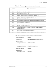
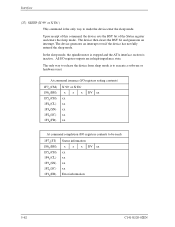
...Disables the advanced power management function. Specifies the transfer of 4-byte ECC for READ LONG and WRITE LONG commands. At power-on or after software reset : Disabled C141-E120-02EN 5-41 5.3 Host Commands Table 5.5 Features register values and settable modes Features Register X'02' X'03' ...' X'42' X'55' X'66' X'82' X'85' X'AA' X'BB' X'C2' X'CC' Drive operation mode Enables the write cache function. Disables the Acoustic management function. Enables the reverting to power-on default settings after software reset. Disables the reverting to power-on default settings after...
...Disables the advanced power management function. Specifies the transfer of 4-byte ECC for READ LONG and WRITE LONG commands. At power-on or after software reset : Disabled C141-E120-02EN 5-41 5.3 Host Commands Table 5.5 Features register values and settable modes Features Register X'02' X'03' ...' X'42' X'55' X'66' X'82' X'85' X'AA' X'BB' X'C2' X'CC' Drive operation mode Enables the write cache function. Disables the Acoustic management function. Enables the reverting to power-on default settings after software reset. Disables the reverting to power-on default settings after...

Manual/User Guide
Page 119
5.3 Host Commands Multiword DMA transfer mode X Ultra DMA transfer mode X 00100 000 (X'20': Mode 0) 00100 001 (X'21': Mode 1) 00100 010 (X'22': Mode 2) 01000 000 (X'40': Mode 0) 01000 001 (X'41': Mode 1) 01000 010 (X'42': Mode 2) 01000 011 (X'43': Mode 3) ...-3Fh FFh, 00h Active Idle Low Power Idle Standby : The spindle motor is rotating and heads are loaded on , hardware and software resets. The power management level is preserved by the drive across power on the medium. : The spindle motor is rotating and heads are unloaded from the ramp. : The spindle motor...
5.3 Host Commands Multiword DMA transfer mode X Ultra DMA transfer mode X 00100 000 (X'20': Mode 0) 00100 001 (X'21': Mode 1) 00100 010 (X'22': Mode 2) 01000 000 (X'40': Mode 0) 01000 001 (X'41': Mode 1) 01000 010 (X'42': Mode 2) 01000 011 (X'43': Mode 3) ...-3Fh FFh, 00h Active Idle Low Power Idle Standby : The spindle motor is rotating and heads are loaded on , hardware and software resets. The power management level is preserved by the drive across power on the medium. : The spindle motor is rotating and heads are unloaded from the ramp. : The spindle motor...
Manual/User Guide
Page 120
... MULTIPLE commands. When the SET MULTIPLE MODE command operation is issued, the READ MULTIPLE and WRITE MULTIPLE commands are also specified by the drive across power on, hardware and software resets. AAM Level Standard Seek Slow Seek Reserved Sector Count register C0h-FEh, 00h 80h-BFh 01h-7Fh, FFh Standard Seek Slow...
... MULTIPLE commands. When the SET MULTIPLE MODE command operation is issued, the READ MULTIPLE and WRITE MULTIPLE commands are also specified by the drive across power on, hardware and software resets. AAM Level Standard Seek Slow Seek Reserved Sector Count register C0h-FEh, 00h 80h-BFh 01h-7Fh, FFh Standard Seek Slow...
Manual/User Guide
Page 138
... motor is stopped and the ATA interface section is the only way to make the device enter the sleep mode. All I /O registers contents to execute a software or hardware reset. The device generates an interrupt even if the device has not fully entered the sleep mode. At command issuance (I/O registers setting contents...
... motor is stopped and the ATA interface section is the only way to make the device enter the sleep mode. All I /O registers contents to execute a software or hardware reset. The device generates an interrupt even if the device has not fully entered the sleep mode. At command issuance (I/O registers setting contents...
Manual/User Guide
Page 161
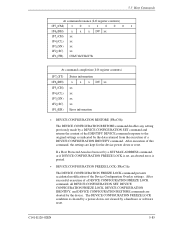
...; DEVICE CONFIGURATION FREEZE LOCK (FR=C1h) The DEVICE CONFIGURATION FREEZE LOCK command prevents accidental modification of this command, the settings are aborted by a hardware or software reset.
...; DEVICE CONFIGURATION FREEZE LOCK (FR=C1h) The DEVICE CONFIGURATION FREEZE LOCK command prevents accidental modification of this command, the settings are aborted by a hardware or software reset.
Manual/User Guide
Page 175
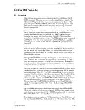
... These signal lines revert back to the Ultra DMA data burst only. All of supporting. During an Ultra DMA burst a sender shall always drive data onto the bus, and after a sufficient time to allow for propagation delay, cable settling, and setup time, the sender shall generate a...of an Ultra DMA burst. All timing requirements for data transfers so that drives the data onto the bus. An Ultra DMA capable device shall retain its CRC data to its default nonUltra DMA Modes after executing a Software reset sequence. 5.5 Ultra DMA Feature Set 5.5 Ultra DMA Feature Set 5.5.1...
... These signal lines revert back to the Ultra DMA data burst only. All of supporting. During an Ultra DMA burst a sender shall always drive data onto the bus, and after a sufficient time to allow for propagation delay, cable settling, and setup time, the sender shall generate a...of an Ultra DMA burst. All timing requirements for data transfers so that drives the data onto the bus. An Ultra DMA capable device shall retain its CRC data to its default nonUltra DMA Modes after executing a Software reset sequence. 5.5 Ultra DMA Feature Set 5.5 Ultra DMA Feature Set 5.5.1...

Manual/User Guide
Page 202
...400 ns - 1 ms - 30 s - 400 ms - 31 s Figure 5.21 Power-on -Reset, Hardware Reset (RESET-), and Software Reset. (2) Master and slave devices are present (2-drives configuration) [Master device] BSY DASP- [Slave device] BSY PDIAG- negation to DASP- assertion (slave device) tS Duration of RESETtN Time from...diagnostics execution time tR Time from RESET- Interface 5.6.4 Power-on and reset Figure 5.21 shows power-on and reset (hardware and software reset) timing. (1) Only master device is present Clear Reset *1 Power-on RESETSoftware reset BSY tM tN DASPtP *1: Reset means ...
...400 ns - 1 ms - 30 s - 400 ms - 31 s Figure 5.21 Power-on -Reset, Hardware Reset (RESET-), and Software Reset. (2) Master and slave devices are present (2-drives configuration) [Master device] BSY DASP- [Slave device] BSY PDIAG- negation to DASP- assertion (slave device) tS Duration of RESETtN Time from...diagnostics execution time tR Time from RESET- Interface 5.6.4 Power-on and reset Figure 5.21 shows power-on and reset (hardware and software reset) timing. (1) Only master device is present Clear Reset *1 Power-on RESETSoftware reset BSY tM tN DASPtP *1: Reset means ...
Manual/User Guide
Page 207
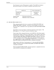
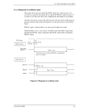
... sec. signal when asserting the PDIAG- X'3F6' Reg. is set to the master device as described below: PDIAG- After the slave device receives the software reset, the slave device shall report its presence and the result of the self-diagnostics to a slave device, the IDD asserts the DASP- Master device... X"0C" or X"04" X"00" Status Reg. signal for up to 15 seconds to software reset The master device does not check the DASP- signal, and negates the DASP- If the slave device is present, the master device checks the...
... sec. signal when asserting the PDIAG- X'3F6' Reg. is set to the master device as described below: PDIAG- After the slave device receives the software reset, the slave device shall report its presence and the result of the self-diagnostics to a slave device, the IDD asserts the DASP- Master device... X"0C" or X"04" X"00" Status Reg. signal for up to 15 seconds to software reset The master device does not check the DASP- signal, and negates the DASP- If the slave device is present, the master device checks the...
Manual/User Guide
Page 210
...mode is minimal in the sleep mode. Operations takes longer than the active or Idle mode because the access to execute a software or hardware reset. The drive enters the standby mode under the following condition: • A SLEEP command is issued in this mode. 6.2.2 Power commands... in the standby mode. • Reset (hardware or software) • STANDBY command • STANDBY IMMEDIATE command • INITIALIZE DEVICE PARAMETERS command • CHECK POWER MODE command (4) Sleep mode The power consumption of the drive is to the disk medium cannot be made immediately. Issued...
...mode is minimal in the sleep mode. Operations takes longer than the active or Idle mode because the access to execute a software or hardware reset. The drive enters the standby mode under the following condition: • A SLEEP command is issued in this mode. 6.2.2 Power commands... in the standby mode. • Reset (hardware or software) • STANDBY command • STANDBY IMMEDIATE command • INITIALIZE DEVICE PARAMETERS command • CHECK POWER MODE command (4) Sleep mode The power consumption of the drive is to the disk medium cannot be made immediately. Issued...