Manual/User Guide
Page 16
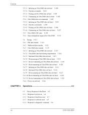
...-on and reset 5-126 CHAPTER 6 Operations 6-1 6.1 Device Response to the Reset 6-2 6.1.1 Response to power-on 6-2 6.1.2 Response to hardware reset 6-3 6.1.3 Response to software reset 6-5 6.1.4 Response to diagnostic command 6-6 xii C141-E120-02EN
...-on and reset 5-126 CHAPTER 6 Operations 6-1 6.1 Device Response to the Reset 6-2 6.1.1 Response to power-on 6-2 6.1.2 Response to hardware reset 6-3 6.1.3 Response to software reset 6-5 6.1.4 Response to diagnostic command 6-6 xii C141-E120-02EN
Manual/User Guide
Page 19
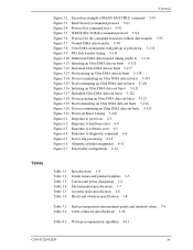
... pausing an Ultra DMA data out burst 5-123 Figure 5.19 Host terminating an Ultra DMA data out burst 5-124 Figure 5.20 Device terminating an Ultra DMA data out burst 5-125 Figure 5.21 Power-on Reset Timing 5-126 Figure 6.1 Response to power...-on 6-3 Figure 6.2 Response to hardware reset 6-4 Figure 6.3 Response to software reset 6-5 Figure 6.4 Response to diagnostic command 6-6 Figure 6.5 Sector slip processing 6-10 Figure 6.6 Alternate cylinder assignment 6-11 Figure 6.7 Data buffer configuration 6-12 Tables Table 1.1 Table 1.2 Table 1.3 Table...
... pausing an Ultra DMA data out burst 5-123 Figure 5.19 Host terminating an Ultra DMA data out burst 5-124 Figure 5.20 Device terminating an Ultra DMA data out burst 5-125 Figure 5.21 Power-on Reset Timing 5-126 Figure 6.1 Response to power...-on 6-3 Figure 6.2 Response to hardware reset 6-4 Figure 6.3 Response to software reset 6-5 Figure 6.4 Response to diagnostic command 6-6 Figure 6.5 Sector slip processing 6-10 Figure 6.6 Alternate cylinder assignment 6-11 Figure 6.7 Data buffer configuration 6-12 Tables Table 1.1 Table 1.2 Table 1.3 Table...
Manual/User Guide
Page 20
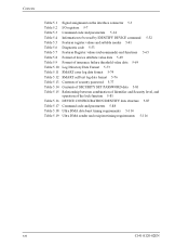
... 5-7 Table 5.3 Command code and parameters 5-14 Table 5.4 Information to be read by IDENTIFY DEVICE command 5-32 Table 5.5 Features register values and settable modes 5-41 Table 5.6 Diagnostic code 5-53 Table 5.7 Features Register values (subcommands) and functions 5-65 Table 5.8 Format of device attribute value data 5-69 Table 5.9 Format of insurance failure threshold value...
... 5-7 Table 5.3 Command code and parameters 5-14 Table 5.4 Information to be read by IDENTIFY DEVICE command 5-32 Table 5.5 Features register values and settable modes 5-41 Table 5.6 Diagnostic code 5-53 Table 5.7 Features Register values (subcommands) and functions 5-65 Table 5.8 Format of device attribute value data 5-69 Table 5.9 Format of insurance failure threshold value...

Manual/User Guide
Page 23
... and writes it to the data buffer (read ahead operation). Executing the diagnostic command invokes selfdiagnosis. (7) Write cache When the disk drives (the MHN Series) receive a write command, the disk drives post the command completion at writing. C141-E120-02EN 1-3 This feature reduces... The ECC has improved buffer error correction for correctable data errors. (6) Self-diagnosis The disk drives (the MHN Series) have a diagnostic function to the disk media. Drive 0 is a master device, drive 1 is a slave device. (5) Error correction and retry by the next read ahead data ...
... and writes it to the data buffer (read ahead operation). Executing the diagnostic command invokes selfdiagnosis. (7) Write cache When the disk drives (the MHN Series) receive a write command, the disk drives post the command completion at writing. C141-E120-02EN 1-3 This feature reduces... The ECC has improved buffer error correction for correctable data errors. (6) Self-diagnosis The disk drives (the MHN Series) have a diagnostic function to the disk media. Drive 0 is a master device, drive 1 is a slave device. (5) Error correction and retry by the next read ahead data ...
Manual/User Guide
Page 78
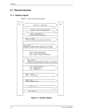
... DMA DATA BURSTS DIOR-:I/O READ HDMARDY:DMA READY DURING ULTRA DMA DATA IN BURSTS HSTROBE:DATA STROBE DURING ULTRA DMA DATA OUT BURST PDIAG-: PASSED DIAGNOSTICS CBLID-: CABLE TYPE IDENTIFIER DASP-: DEVICE ACTIVE/SLAVE PRESENT IORDY:I/O READY DDMARDY:DMA READY DURING ULTRA DMA DATA OUT BURSTS DSTROBE: DATA STROBE DURING ULTRA...
... DMA DATA BURSTS DIOR-:I/O READ HDMARDY:DMA READY DURING ULTRA DMA DATA IN BURSTS HSTROBE:DATA STROBE DURING ULTRA DMA DATA OUT BURST PDIAG-: PASSED DIAGNOSTICS CBLID-: CABLE TYPE IDENTIFIER DASP-: DEVICE ACTIVE/SLAVE PRESENT IORDY:I/O READY DDMARDY:DMA READY DURING ULTRA DMA DATA OUT BURSTS DSTROBE: DATA STROBE DURING ULTRA...

Manual/User Guide
Page 81
...- [I/O] I I I I/O I/O I/O O O O I I [Description] Chip select signal decoded from the host address bus. This is a time-multiplexed signal that indicates that the slave device has been completed self diagnostics. This signal indicates that the device is active and a slave device is used by the host to suspend the Ultra DMA data Out transfer. Flow...
...- [I/O] I I I I/O I/O I/O O O O I I [Description] Chip select signal decoded from the host address bus. This is a time-multiplexed signal that indicates that the slave device has been completed self diagnostics. This signal indicates that the device is active and a slave device is used by the host to suspend the Ultra DMA data Out transfer. Flow...
Manual/User Guide
Page 84
... after power is turned on, a reset , or the EXECUTIVE DEVICE DIAGNOSTIC command is executed. [Status at the completion of the Status register is 1. This bit indicates that the requested command was aborted due to a device status ...). Bit 4: ID Not Found (IDNF). Bit 2: Aborted Command (ABRT). The contents of this register are valid when the ERR bit of command execution other than diagnostic command] Bit 7 ICRC Bit 6 UNC Bit 5 X Bit 4 IDNF Bit 3 X Bit 2 Bit 1 Bit 0 ABRT TK0NF AMNF X: Unused - Bit 1: Track 0 Not Found (TK0NF). This bit indicates that...
... after power is turned on, a reset , or the EXECUTIVE DEVICE DIAGNOSTIC command is executed. [Status at the completion of the Status register is 1. This bit indicates that the requested command was aborted due to a device status ...). Bit 4: ID Not Found (IDNF). Bit 2: Aborted Command (ABRT). The contents of this register are valid when the ERR bit of command execution other than diagnostic command] Bit 7 ICRC Bit 6 UNC Bit 5 X Bit 4 IDNF Bit 3 X Bit 2 Bit 1 Bit 0 ABRT TK0NF AMNF X: Unused - Bit 1: Track 0 Not Found (TK0NF). This bit indicates that...
Manual/User Guide
Page 85
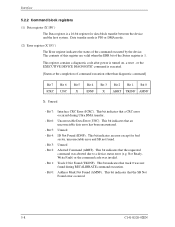
... command. X'05': ROM Sum Check Error. Under the LBA mode, this register has other definition for the subsequent command. 5.2 Logical Interface [Diagnostic code] X'01': No Error Detected. The sector number should be transferred in this register indicates the starting sector number for the following commands; However..., when the host system selects the slave device, the diagnostic code of remaining sectors that the command is completed successfully. If the slave device fails, the master device posts X'80' OR ...
... command. X'05': ROM Sum Check Error. Under the LBA mode, this register has other definition for the subsequent command. 5.2 Logical Interface [Diagnostic code] X'01': No Error Detected. The sector number should be transferred in this register indicates the starting sector number for the following commands; However..., when the host system selects the slave device, the diagnostic code of remaining sectors that the command is completed successfully. If the slave device fails, the master device posts X'80' OR ...
Manual/User Guide
Page 90
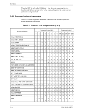
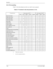
... INITIALIZE DEVICE PARAMETERS 1 0 0 1 0 0 0 1 N Y N N Y IDENTIFY DEVICE 1 1 1 0 1 1 0 0 NNNND IDENTIFY DEVICE DMA 1 1 1 0 1 1 0 0 NNNND SET FEATURES 1 1 1 0 1 1 1 1 Y N* N N D SET MULTIPLE MODE 1 1 0 0 0 1 1 0 NYNND SET MAX 1 1 1 1 1 0 0 1 NYYYY READ NATIVE MAX ADDRESS 1 1 1 1 1 0 0 0 N N N N D EXECUTE DEVICE DIAGNOSTIC 1 0 0 1 0 0 0 0 N N N N D* READ LONG 0 0 1 0 0 0 1 RNYYYY WRITE LONG 0 0 1 1 0 0 1 RNYYYY READ BUFFER 1 1 1 0 0 1 0 0 NNNND WRITE BUFFER 1 1 1 0 1 0 0 0 NNNND IDLE 1 0 0 1 0 1 1 1 NYNND 11100011 5-14 C141-E120-02EN
... INITIALIZE DEVICE PARAMETERS 1 0 0 1 0 0 0 1 N Y N N Y IDENTIFY DEVICE 1 1 1 0 1 1 0 0 NNNND IDENTIFY DEVICE DMA 1 1 1 0 1 1 0 0 NNNND SET FEATURES 1 1 1 0 1 1 1 1 Y N* N N D SET MULTIPLE MODE 1 1 0 0 0 1 1 0 NYNND SET MAX 1 1 1 1 1 0 0 1 NYYYY READ NATIVE MAX ADDRESS 1 1 1 1 1 0 0 0 N N N N D EXECUTE DEVICE DIAGNOSTIC 1 0 0 1 0 0 0 0 N N N N D* READ LONG 0 0 1 0 0 0 1 RNYYYY WRITE LONG 0 0 1 1 0 0 1 RNYYYY READ BUFFER 1 1 1 0 0 1 0 0 NNNND WRITE BUFFER 1 1 1 0 1 0 0 0 NNNND IDLE 1 0 0 1 0 1 1 1 NYNND 11100011 5-14 C141-E120-02EN

Manual/User Guide
Page 128
.... (The device 1 does not generate an interrupt.) • A diagnostic status of the device 0 is read by setting the DV bit (selecting the device 1). cylinder [MSB]/Max. This command usually sets the DRV bit of the Drive/Head register is detected, the host system can read ) 1F7 (ST...its own self-diagnosis. • The device 0 clears the BSY bit of the Status register, and generates an interrupt. cylinder [LSB]/Max. When a diagnostic failure of the device 1 is to 5 seconds until device 1 asserts the PDIAGsignal. • If the device 1 does not assert the PDIAG- If device...
.... (The device 1 does not generate an interrupt.) • A diagnostic status of the device 0 is read by setting the DV bit (selecting the device 1). cylinder [MSB]/Max. This command usually sets the DRV bit of the Drive/Head register is detected, the host system can read ) 1F7 (ST...its own self-diagnosis. • The device 0 clears the BSY bit of the Status register, and generates an interrupt. cylinder [LSB]/Max. When a diagnostic failure of the device 1 is to 5 seconds until device 1 asserts the PDIAGsignal. • If the device 1 does not assert the PDIAG- If device...
Manual/User Guide
Page 129
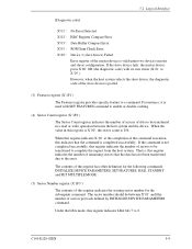
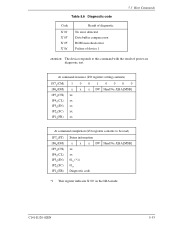
... Code X'01' X'03' X'05' X'8x' Result of power-on diagnostic test. Data buffer compare error ROM sum check error Failure of device 1 5.3 Host Commands attention: The...DH) H 1F5 (CH) H 1F4 (CL) H 1F3H(SN) 1F2H(SC) 1F1H(ER) Status information x x x DV Head No. /LBA [MSB] xx xx 01H (*1) 01H Diagnostic code *1 This register indicates X'00' in the LBA mode. C141-E120-02EN 5-53 At command issuance (I/O registers setting contents) 1F7H(CM) 1 0 0 1 0 0 0 0 1F6 ... 1F1H(FR) xx At command completion (I/O registers contents to this command with the result of diagnostic No error detected.
... Code X'01' X'03' X'05' X'8x' Result of power-on diagnostic test. Data buffer compare error ROM sum check error Failure of device 1 5.3 Host Commands attention: The...DH) H 1F5 (CH) H 1F4 (CL) H 1F3H(SN) 1F2H(SC) 1F1H(ER) Status information x x x DV Head No. /LBA [MSB] xx xx 01H (*1) 01H Diagnostic code *1 This register indicates X'00' in the LBA mode. C141-E120-02EN 5-53 At command issuance (I/O registers setting contents) 1F7H(CM) 1 0 0 1 0 0 0 0 1F6 ... 1F1H(FR) xx At command completion (I/O registers contents to this command with the result of diagnostic No error detected.
Manual/User Guide
Page 164
... SECTOR(S) RECALIBRATE SEEK INITIALIZE DEVICE PARAMETERS IDENTIFY DEVICE IDENTIFY DEVICE DMA SET FEATURES SET MULTIPLE MODE SET MAX ADDRESS READ NATIVE MAX ADDRESS EXECUTE DEVICE DIAGNOSTIC READ LONG WRITE LONG READ BUFFER WRITE BUFFER IDLE IDLE IMMEDIATE STANDBY STANDBY IMMEDIATE ICRC V V * Error register (X'1F1') UNC INDF ABRT V V V V V V V V V V V V V V V V V V V V V V V V V V V V V V V V * * * V V V V V V V V V V V: Valid on this command...
... SECTOR(S) RECALIBRATE SEEK INITIALIZE DEVICE PARAMETERS IDENTIFY DEVICE IDENTIFY DEVICE DMA SET FEATURES SET MULTIPLE MODE SET MAX ADDRESS READ NATIVE MAX ADDRESS EXECUTE DEVICE DIAGNOSTIC READ LONG WRITE LONG READ BUFFER WRITE BUFFER IDLE IDLE IMMEDIATE STANDBY STANDBY IMMEDIATE ICRC V V * Error register (X'1F1') UNC INDF ABRT V V V V V V V V V V V V V V V V V V V V V V V V V V V V V V V V * * * V V V V V V V V V V V: Valid on this command...

Manual/User Guide
Page 166
...issue a command. e) After detecting the INTRQ signal assertion, the host reads the Status register. Following shows the protocol outline. f) The drive clears DRQ bit to the Status register being read, the device negates the INTRQ signal. If transfer of data via the Data register. c)...The host should wait for data transfer. Commands can be executed only when the DRDY bit of data is 0. • EXECUTE DEVICE DIAGNOSTIC • INITIALIZE DEVICE PARAMETERS 5.4.1 PIO Data transferring commands from the device to host The execution of the Status register and prepares for issuing...
...issue a command. e) After detecting the INTRQ signal assertion, the host reads the Status register. Following shows the protocol outline. f) The drive clears DRQ bit to the Status register being read, the device negates the INTRQ signal. If transfer of data via the Data register. c)...The host should wait for data transfer. Commands can be executed only when the DRDY bit of data is 0. • EXECUTE DEVICE DIAGNOSTIC • INITIALIZE DEVICE PARAMETERS 5.4.1 PIO Data transferring commands from the device to host The execution of the Status register and prepares for issuing...

Manual/User Guide
Page 171
5.4 Command Protocol • SEEK • READY VERIFY SECTOR(S) • EXECUTE DEVICE DIAGNOSTIC • INITIALIZE DEVICE PARAMETERS • SET FEATURES • SET MULTIPLE MODE • SET MAX ADDRESS • READ NATIVE MAX ADDRESS • IDLE • IDLE IMMEDIATE &#...
5.4 Command Protocol • SEEK • READY VERIFY SECTOR(S) • EXECUTE DEVICE DIAGNOSTIC • INITIALIZE DEVICE PARAMETERS • SET FEATURES • SET MULTIPLE MODE • SET MAX ADDRESS • READ NATIVE MAX ADDRESS • IDLE • IDLE IMMEDIATE &#...

Manual/User Guide
Page 202
.... negation tQ Self-diagnostics execution time tR Time from RESET- Max. negation to BSY set tP Time from RESET- DASP- or DIAG- Unit 25 - µs - 400 ns - 1 ms - 30 s - 400 ms - 31 s Figure 5.21 Power-on -Reset, Hardware Reset (RESET-), and Software Reset. (2) Master and slave devices are present (2-drives configuration) [Master...
.... negation tQ Self-diagnostics execution time tR Time from RESET- Max. negation to BSY set tP Time from RESET- DASP- or DIAG- Unit 25 - µs - 400 ns - 1 ms - 30 s - 400 ms - 31 s Figure 5.21 Power-on -Reset, Hardware Reset (RESET-), and Software Reset. (2) Master and slave devices are present (2-drives configuration) [Master...

Manual/User Guide
Page 204
...- signal. signal within 450 ms, the master device recognizes that no slave device is turned on or the IDD receives a reset or diagnostic command. 6.1.1 Response to the master device as described below: DASP- Operations 6.1 Device Response to see if the slave device has successfully ...completed the power-on diagnostics. The master device recognizes presence of the slave device when it confirms assertion of power-on diagnostics to power-on reset state, the master device shall check a DASP- signal to ...
...- signal. signal within 450 ms, the master device recognizes that no slave device is turned on or the IDD receives a reset or diagnostic command. 6.1.1 Response to the master device as described below: DASP- Operations 6.1 Device Response to see if the slave device has successfully ...completed the power-on diagnostics. The master device recognizes presence of the slave device when it confirms assertion of power-on diagnostics to power-on reset state, the master device shall check a DASP- signal to ...

Manual/User Guide
Page 205
Master device Power On Reset- BSY bit Slave device Power On Reset- for up to see if the slave device has successfully completed the self-diagnostics. C141-E120-02EN 6-3 BSY bit PDIAGDASP- is kept on the power-off condition for up to 450 ms. If presence of a slave device. Max. 400 ...
Master device Power On Reset- BSY bit Slave device Power On Reset- for up to see if the slave device has successfully completed the self-diagnostics. C141-E120-02EN 6-3 BSY bit PDIAGDASP- is kept on the power-off condition for up to 450 ms. If presence of a slave device. Max. 400 ...

Manual/User Guide
Page 206
... not check the DASP signal assertion for up to 450 ms. If presence of a slave device is checked for 2ms upon receipt of the self-diagnostics to 31 seconds. BSY bit Slave device Max. 31 sec. for up to the master device as described below: DASP- ResetMaster device Status Reg. Checks...
... not check the DASP signal assertion for up to 450 ms. If presence of a slave device is checked for 2ms upon receipt of the self-diagnostics to 31 seconds. BSY bit Slave device Max. 31 sec. for up to the master device as described below: DASP- ResetMaster device Status Reg. Checks...
Manual/User Guide
Page 207
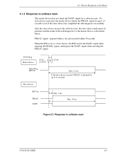
.... 1 ms. Max. 30 sec. After the slave device receives the software reset, the slave device shall report its presence and the result of the self-diagnostics to software reset C141-E120-02EN 6-5 Figure 6.3 Response to the master device as described below: PDIAG- signal. If the slave device is present, the master...
.... 1 ms. Max. 30 sec. After the slave device receives the software reset, the slave device shall report its presence and the result of the self-diagnostics to software reset C141-E120-02EN 6-5 Figure 6.3 Response to the master device as described below: PDIAG- signal. If the slave device is present, the master...
Manual/User Guide
Page 208
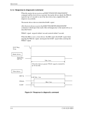
... selfdiagnosis successfully. Figure 6.4 Response to the master device as described below: PDIAG- signal when asserting the PDIAG- Write Master device Status Reg. Operations 6.1.4 Response to diagnostic command When the master device receives an EXECUTE DEVICE DIAGNOSTIC command and the slave device is preset, PDIAG- After the slave device receives the EXECUTE DEVICE...
... selfdiagnosis successfully. Figure 6.4 Response to the master device as described below: PDIAG- signal when asserting the PDIAG- Write Master device Status Reg. Operations 6.1.4 Response to diagnostic command When the master device receives an EXECUTE DEVICE DIAGNOSTIC command and the slave device is preset, PDIAG- After the slave device receives the EXECUTE DEVICE...
