Manual/User Guide
Page 18
... Factory default setting 3-12 Figure 3.13 Jumper setting of master or slave drive 3-12 Figure 3.14 CSEL setting 3-13 Figure 3.15 Example (1) of Cable Select 3-13 Figure 3.16 Example (2) of Cable Select 3-14 Figure 4.1 Figure 4.2 Figure 4.3 Figure 4.4 Figure 4.5 Figure 4.6 Figure 4.7 Figure 4.8 Figure 4.9 Head structure 4-3 Power Supply Configuration 4-5 Circuit Configuration 4-6 Power-on operation sequence 4-8 Read/write circuit block diagram 4-12 Frequency characteristic of programmable filter 4-13 Block diagram of servo control circuit 4-15 Physical sector servo configuration on disk...
... Factory default setting 3-12 Figure 3.13 Jumper setting of master or slave drive 3-12 Figure 3.14 CSEL setting 3-13 Figure 3.15 Example (1) of Cable Select 3-13 Figure 3.16 Example (2) of Cable Select 3-14 Figure 4.1 Figure 4.2 Figure 4.3 Figure 4.4 Figure 4.5 Figure 4.6 Figure 4.7 Figure 4.8 Figure 4.9 Head structure 4-3 Power Supply Configuration 4-5 Circuit Configuration 4-6 Power-on operation sequence 4-8 Read/write circuit block diagram 4-12 Frequency characteristic of programmable filter 4-13 Block diagram of servo control circuit 4-15 Physical sector servo configuration on disk...
Manual/User Guide
Page 22
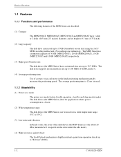
... head positioning mechanism greatly increases the positioning speed. The disk drive supports an external data rate up to 100 MB/s (U-DMA mode 5). (4) Average positioning time Use of 30 GB (MHN2300AT), 20 GB (MHN2200AT), 15 GB (MHN2150AT) and 10 GB (MHN2100AT) respectively. (3) High-speed Transfer rate The disk drives (the MHN Series) have 1 disk or 2 disks of the disk drives (the MHN Series) is only about 24 dBA (measured at read). 1.1.2 Adaptability (1) Power save mode The power save mode feature for idle operation, stand by and sleep modes makes...
... head positioning mechanism greatly increases the positioning speed. The disk drive supports an external data rate up to 100 MB/s (U-DMA mode 5). (4) Average positioning time Use of 30 GB (MHN2300AT), 20 GB (MHN2200AT), 15 GB (MHN2150AT) and 10 GB (MHN2100AT) respectively. (3) High-speed Transfer rate The disk drives (the MHN Series) have 1 disk or 2 disks of the disk drives (the MHN Series) is only about 24 dBA (measured at read). 1.1.2 Adaptability (1) Power save mode The power save mode feature for idle operation, stand by and sleep modes makes...
Manual/User Guide
Page 24
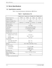
Table 1.1 Specifications (1/2) MHN2300AT MHN2200AT MHN2150AT MHN2100AT Format Capacity (*1) 30 GB 20 GB 15 GB 10 GB Number of Heads 4 3 2 2 Number of Cylinders (User) 28,416 Number of the disk drives (MHN Series). Device Overview 1.2 Device Specifications 1.2.1 Specifications summary Table 1.1 shows the specifications of Sectors (User) 58,605,120 39,070,080 29,498,112 19,640,880 Bytes per Sector 512 Recording Method 16/17 MTR Track Density 1.98 K track/mm (50,400 TPI) Bit Density 22...
Table 1.1 Specifications (1/2) MHN2300AT MHN2200AT MHN2150AT MHN2100AT Format Capacity (*1) 30 GB 20 GB 15 GB 10 GB Number of Heads 4 3 2 2 Number of Cylinders (User) 28,416 Number of the disk drives (MHN Series). Device Overview 1.2 Device Specifications 1.2.1 Specifications summary Table 1.1 shows the specifications of Sectors (User) 58,605,120 39,070,080 29,498,112 19,640,880 Bytes per Sector 512 Recording Method 16/17 MTR Track Density 1.98 K track/mm (50,400 TPI) Bit Density 22...
Manual/User Guide
Page 29
Disk drive defects do not include failures caused by external factors, such as follows: Total operation time in all fields (*1) *1 "Disk drive defects" refers to defects that involve repair, readjustment, or replacement. Also the operating conditions except the environment temperature are based on the MTBF conditions. (4) Data assurance in the event of power failure Except for the data block being written to, the data on time 1/day or more needed. 5 to...
Disk drive defects do not include failures caused by external factors, such as follows: Total operation time in all fields (*1) *1 "Disk drive defects" refers to defects that involve repair, readjustment, or replacement. Also the operating conditions except the environment temperature are based on the MTBF conditions. (4) Data assurance in the event of power failure Except for the data block being written to, the data on time 1/day or more needed. 5 to...
Manual/User Guide
Page 30
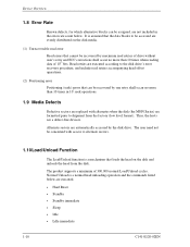
... head from the factory (low level format). Read retries are executed according to the disk drive's error recovery procedure, and include read retries of drive without user's retry and ECC corrections shall occur no more than 10 times in 107 seek operations. 1.9 Media Defects Defective sectors are not included in the error rate count below are automatically accessed by one retry shall occur no more than 10 times when reading data...
... head from the factory (low level format). Read retries are executed according to the disk drive's error recovery procedure, and include read retries of drive without user's retry and ECC corrections shall occur no more than 10 times in 107 seek operations. 1.9 Media Defects Defective sectors are not included in the error rate count below are automatically accessed by one retry shall occur no more than 10 times when reading data...
Manual/User Guide
Page 74
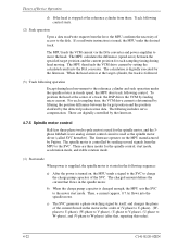
... in the spindle motor. For each sampling timing during head movement to the reference cylinder and seek operation under the spindle rotates in steady speed, the MPU does track following control starts. (2) Seek operation Upon a data read /write instruction is charged enough, the MPU sets the SVC to the motor start mode, acceleration mode, and stable rotation mode. (1) Start mode When power is supplied, the spindle motor is started in...
... in the spindle motor. For each sampling timing during head movement to the reference cylinder and seek operation under the spindle rotates in steady speed, the MPU does track following control starts. (2) Seek operation Upon a data read /write instruction is charged enough, the MPU sets the SVC to the motor start mode, acceleration mode, and stable rotation mode. (1) Start mode When power is supplied, the spindle motor is started in...

Manual/User Guide
Page 82
... setting bit 6 in the Device/Head register to 1, HS3 to the device. "O" indicates output signal from the host to HS0 bits of LBA0 (defined as follows). The IDENTIFY DEVICE information indicates whether the device supports the LBA mode. The DMA data transfer is performed, IOCS16-, CS0- When the host system specifies the LBA mode by the INITIALIZE DEVICE PARAMETER command, the sector LBA address is not changed. The direction of sector/track)] + (Sector...
... setting bit 6 in the Device/Head register to 1, HS3 to the device. "O" indicates output signal from the host to HS0 bits of LBA0 (defined as follows). The IDENTIFY DEVICE information indicates whether the device supports the LBA mode. The DMA data transfer is performed, IOCS16-, CS0- When the host system specifies the LBA mode by the INITIALIZE DEVICE PARAMETER command, the sector LBA address is not changed. The direction of sector/track)] + (Sector...
Manual/User Guide
Page 91
... CHECK POWER MODE 1 0 0 1 1 0 0 0 NNNND 11100101 SMART 1 0 1 1 0 0 0 0 YYYYD SECURITY DISABLE PASSWORD 1 1 1 1 0 1 1 0 N N N N D SECURITY ERASE PREPARE 1 1 1 1 0 0 1 1 NNNND SECURITY ERASE UNIT 1 1 1 1 0 1 0 0 NNNND SECURITY FREEZE LOCK 1 1 1 1 0 1 0 1 NNNND SECURITY SET PASSWORD 1 1 1 1 0 0 0 1 NNNND SECURITY UNLOCK 1 1 1 1 0 0 1 0 NNNND FLUSH CACHE 1 1 1 0 0 1 1 1 NNNND DEVICE CONFIGURATION 1 0 1 1 0 0 0 1 YNNND Notes: FR: Features Register CY: Cylinder Registers SC: Sector Count Register DH: Drive/Head Register SN: Sector Number Register R: Retry at error 1 = Without...
... CHECK POWER MODE 1 0 0 1 1 0 0 0 NNNND 11100101 SMART 1 0 1 1 0 0 0 0 YYYYD SECURITY DISABLE PASSWORD 1 1 1 1 0 1 1 0 N N N N D SECURITY ERASE PREPARE 1 1 1 1 0 0 1 1 NNNND SECURITY ERASE UNIT 1 1 1 1 0 1 0 0 NNNND SECURITY FREEZE LOCK 1 1 1 1 0 1 0 1 NNNND SECURITY SET PASSWORD 1 1 1 1 0 0 0 1 NNNND SECURITY UNLOCK 1 1 1 1 0 0 1 0 NNNND FLUSH CACHE 1 1 1 0 0 1 1 1 NNNND DEVICE CONFIGURATION 1 0 1 1 0 0 0 1 YNNND Notes: FR: Features Register CY: Cylinder Registers SC: Sector Count Register DH: Drive/Head Register SN: Sector Number Register R: Retry at error 1 = Without...

Manual/User Guide
Page 93
... the data transfer regardless of sectors specified in the Device/Head, Cylinder High, Cylinder Low and Sector Number registers. The DRQ bit of the R bit setting. Upon the completion of the command execution, command block registers contain the cylinder, head, and sector addresses (in the CHS mode) or logical block address (in a sector, the read operation is always set ) Note: 1. If the head is specified. If an unrecoverable error occurs in the LBA mode...
... the data transfer regardless of sectors specified in the Device/Head, Cylinder High, Cylinder Low and Sector Number registers. The DRQ bit of the R bit setting. Upon the completion of the command execution, command block registers contain the cylinder, head, and sector addresses (in the CHS mode) or logical block address (in a sector, the read operation is always set ) Note: 1. If the head is specified. If an unrecoverable error occurs in the LBA mode...
Manual/User Guide
Page 98
... in the Device/Head, Cylinder High, Cylinder Low, and Sector Number registers to data transfer, see Subsection 5.4.2. If an error occurs when writing to 256 sectors. Number of sectors can be read) 1F7H(ST) 1F6 (DH) H 1F5H(CH) 1F4 (CL) H 1F3 (SN) H 1F2 (SC) H 1F1H(ER) Status information x L x DV End head No. / LBA [MSB] End cylinder No. [MSB] / LBA End cylinder No. [LSB] / LBA End sector No. / LBA [LSB] 00 (*1) Error information *1 If the command is...
... in the Device/Head, Cylinder High, Cylinder Low, and Sector Number registers to data transfer, see Subsection 5.4.2. If an error occurs when writing to 256 sectors. Number of sectors can be read) 1F7H(ST) 1F6 (DH) H 1F5H(CH) 1F4 (CL) H 1F3 (SN) H 1F2 (SC) H 1F1H(ER) Status information x L x DV End head No. / LBA [MSB] End cylinder No. [MSB] / LBA End cylinder No. [LSB] / LBA End sector No. / LBA [LSB] 00 (*1) Error information *1 If the command is...
Manual/User Guide
Page 109
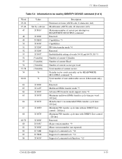
...' X'5B08' X'4003' Description Firmware revision (ASCII code, 8 characters, left) Model name (ASCII code, 40 characters, left) Maximum number of sectors per interrupt on READ/WRITE MULTIPLE command Reserved Capabilities *3 Capabilities PIO data transfer mode *4 Reserved Enable/disable setting of words 54-58 and 64-70, 88 *5 Number of current Cylinders Number of current Head Number of current sectors per track Total number of current sectors Transfer sector count currently set by IDENTIFY DEVICE command (2 of command sets/function *12 C141...
...' X'5B08' X'4003' Description Firmware revision (ASCII code, 8 characters, left) Model name (ASCII code, 40 characters, left) Maximum number of sectors per interrupt on READ/WRITE MULTIPLE command Reserved Capabilities *3 Capabilities PIO data transfer mode *4 Reserved Enable/disable setting of words 54-58 and 64-70, 88 *5 Number of current Cylinders Number of current Head Number of current sectors per track Total number of current sectors Transfer sector count currently set by IDENTIFY DEVICE command (2 of command sets/function *12 C141...
Manual/User Guide
Page 112
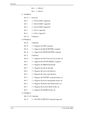
... READ BUFFER command. Bit 0: '1' = Supports the SMART feature set . Bit 12: '1' = Supports the WRITE BUFFER command. Bit 9: '1' = Supports the DEVICE RESET command. Bit 1: '1' = Supports the Security Mode feature set . Bit 8: '1' = Supports the SERVICE interrupt. Bit 6: '1' = Supports the read cache function. Bit 7: '1' = Supports the release interrupt. Bit 2: '1' = Supports the Removable Media feature set . Bit 11: Undefined Bit 10: '1' = Supports the Host Protected Area feature set . Interface Bit 1: 1 = Mode 4 Bit 0: 1 = Mode 3 *9 WORD 80 Bit 15-7: Reserved Bit 6: 1 = ATA...
... READ BUFFER command. Bit 0: '1' = Supports the SMART feature set . Bit 12: '1' = Supports the WRITE BUFFER command. Bit 9: '1' = Supports the DEVICE RESET command. Bit 1: '1' = Supports the Security Mode feature set . Bit 8: '1' = Supports the SERVICE interrupt. Bit 6: '1' = Supports the read cache function. Bit 7: '1' = Supports the release interrupt. Bit 2: '1' = Supports the Removable Media feature set . Bit 11: Undefined Bit 10: '1' = Supports the Host Protected Area feature set . Interface Bit 1: 1 = Mode 4 Bit 0: 1 = Mode 3 *9 WORD 80 Bit 15-7: Reserved Bit 6: 1 = ATA...

Manual/User Guide
Page 116
Table 5.5 lists the available values and operational modes that may be executed. Then, the device clears the BSY bit, and generates an interrupt. Interface Bit 4: Bit 3: Bit 2: Bit 1: Bit 0: '1' = Security counter expired '1' = Security frozen '1' = Security locked '1' = Security enabled '1' = Security supported (14) SET FEATURES (X'EF') The host system issues the SET FEATURES command to set parameters in the Features register for the purpose of the Status register and saves...
Table 5.5 lists the available values and operational modes that may be executed. Then, the device clears the BSY bit, and generates an interrupt. Interface Bit 4: Bit 3: Bit 2: Bit 1: Bit 0: '1' = Security counter expired '1' = Security frozen '1' = Security locked '1' = Security enabled '1' = Security supported (14) SET FEATURES (X'EF') The host system issues the SET FEATURES command to set parameters in the Features register for the purpose of the Status register and saves...
Manual/User Guide
Page 121
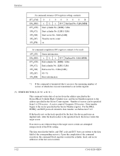
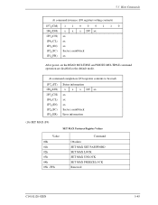
... Value 00h 01h 02h 03h 04h 05h - FFh Command Obsolete SET MAX SET PASSWORD SET MAX LOCK SET MAX UNLOCK SET MAX FREEZE LOCK Reserved C141-E120-02EN 5-45 At command completion (I /O registers setting contents) 1F7 (CM) 1 1 0 0 0 1 1 0 H 1F6H(DH) x x x DV xx 1F5H(CH) xx 1F4H(CL) xx 1F3H(SN) xx 1F2 (SC) Sector count/block H 1F1 (FR) xx H After power-on the READ MULTIPLE and WRITE MULTIPLE command operation are disabled as the default mode.
... Value 00h 01h 02h 03h 04h 05h - FFh Command Obsolete SET MAX SET PASSWORD SET MAX LOCK SET MAX UNLOCK SET MAX FREEZE LOCK Reserved C141-E120-02EN 5-45 At command completion (I /O registers setting contents) 1F7 (CM) 1 1 0 0 0 1 1 0 H 1F6H(DH) x x x DV xx 1F5H(CH) xx 1F4H(CL) xx 1F3H(SN) xx 1F2 (SC) Sector count/block H 1F1 (FR) xx H After power-on the READ MULTIPLE and WRITE MULTIPLE command operation are disabled as the default mode.

Manual/User Guide
Page 122
...) 11111001 x L x DV Max head/LBA [MSB] Max. This command allows the maximum address accessible by this command with VV bit = 1 is made to be set when VV bit = 1. Then, it clears BSY and generates an interrupt. If an attempt is issued twice or more, any command following the first time will result. The new address information set by the user to perform a read or write operation for an...
...) 11111001 x L x DV Max head/LBA [MSB] Max. This command allows the maximum address accessible by this command with VV bit = 1 is made to be set when VV bit = 1. Then, it clears BSY and generates an interrupt. If an attempt is issued twice or more, any command following the first time will result. The new address information set by the user to perform a read or write operation for an...
Manual/User Guide
Page 157
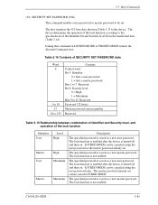
... enabled. The device determines the operation of the lock function according to 255 Contents Control word Bit 0 Identifier 0 = Sets a user password. 1 = Sets a master password. LOCKED MODE can be canceled using the user password only. The specified password is saved as a new master password. Table 5.14 Contents of SECURITY SET PASSWORD data Word 0 1 to 16 17 18 to the specifications of the lock function Identifier User Master User Master Level High High Maximum Maximum Description The specified password is saved as a new user password. The lock...
... enabled. The device determines the operation of the lock function according to 255 Contents Control word Bit 0 Identifier 0 = Sets a user password. 1 = Sets a master password. LOCKED MODE can be canceled using the user password only. The specified password is saved as a new master password. Table 5.14 Contents of SECURITY SET PASSWORD data Word 0 1 to 16 17 18 to the specifications of the lock function Identifier User Master User Master Level High High Maximum Maximum Description The specified password is saved as a new user password. The lock...

Manual/User Guide
Page 158
...(CH) xx 1F4h(CL) xx 1F3h(SN) xx 1F2 (SC) xx h 1F1 (FR) xx h At command completion (I-O register contents) 1F7h(ST) 1F6 (DH) h 1F5h(CH) 1F4 (CL) h 1F3 (SN) h 1F2 (SC) h 1F1h(ER) Status information x x x DV xx xx xx xx xx Error information (35) SECURITY UNLOCK This command cancels LOCKED MODE. Otherwise, the Aborted Command error is compared with the master password already set.
...(CH) xx 1F4h(CL) xx 1F3h(SN) xx 1F2 (SC) xx h 1F1 (FR) xx h At command completion (I-O register contents) 1F7h(ST) 1F6 (DH) h 1F5h(CH) 1F4 (CL) h 1F3 (SN) h 1F2 (SC) h 1F1h(ER) Status information x x x DV xx xx xx xx xx Error information (35) SECURITY UNLOCK This command cancels LOCKED MODE. Otherwise, the Aborted Command error is compared with the master password already set.
Manual/User Guide
Page 161
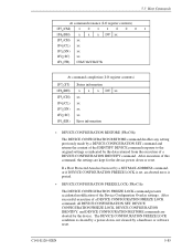
... command, all DEVICE CONFIGURATION SET, DEVICE CONFIGURATION FREEZE LOCK, DEVICE CONFIGURATION IDENTIFY, and DEVICE CONFIGURATION RESTORE commands are kept for the device power down , not cleared by a hardware or software reset. The DEVICE CONFIGURATION FREEZE LOCK condition is posted. • DEVICE CONFIGURATION FREEZE LOCK (FR=C1h) The DEVICE CONFIGURATION FREEZE LOCK command prevents accidental modification of the Device Configuration Overlay settings. If a Host Protected Area has been set by a SET MAX ADDRESS command, or if DEVICE CONFIGURATION FREEZE LOCK is set, an aborted error...
... command, all DEVICE CONFIGURATION SET, DEVICE CONFIGURATION FREEZE LOCK, DEVICE CONFIGURATION IDENTIFY, and DEVICE CONFIGURATION RESTORE commands are kept for the device power down , not cleared by a hardware or software reset. The DEVICE CONFIGURATION FREEZE LOCK condition is posted. • DEVICE CONFIGURATION FREEZE LOCK (FR=C1h) The DEVICE CONFIGURATION FREEZE LOCK command prevents accidental modification of the Device Configuration Overlay settings. If a Host Protected Area has been set by a SET MAX ADDRESS command, or if DEVICE CONFIGURATION FREEZE LOCK is set, an aborted error...

Manual/User Guide
Page 165
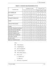
5.3 Host Commands Table 5.17 Command code and parameters (2 of 2) Command name SLEEP CHECK POWER MODE SMART SECURITY DISABLE PASSWORD SECURITY ERASE PREPARE SECURITY ERASE UNIT SECURITY FREEZE LOCK SECURITY SET PASSWORD SECURITY UNLOCK FLUSH CACHE DEVICE CONFIGURATION Invalid command ICRC Error register (X'1F1') UNC INDF ABRT V V V V V V V V V V V V V V V: Valid on this command *: See the command descriptions. TK0NF Status register (X'1F7') DRDY DWF ERR V V V V V V V V V V V V V V V V V V V V V V V V V V V V V V V V V V V V C141-...
5.3 Host Commands Table 5.17 Command code and parameters (2 of 2) Command name SLEEP CHECK POWER MODE SMART SECURITY DISABLE PASSWORD SECURITY ERASE PREPARE SECURITY ERASE UNIT SECURITY FREEZE LOCK SECURITY SET PASSWORD SECURITY UNLOCK FLUSH CACHE DEVICE CONFIGURATION Invalid command ICRC Error register (X'1F1') UNC INDF ABRT V V V V V V V V V V V V V V V: Valid on this command *: See the command descriptions. TK0NF Status register (X'1F7') DRDY DWF ERR V V V V V V V V V V V V V V V V V V V V V V V V V V V V V V V V V V V V C141-...

Manual/User Guide
Page 166
... writes a command code to the Features, Sector Count, Sector Number, Cylinder, and Device/Head registers. Whether or not to transfer the data is determined for issuing a command until BSY bit is cleared to the host. c) The device sets the BSY bit of data from the device to the host. • IDENTIFY DEVICE. • READ SECTOR(S) • READ LONG • READ BUFFER • SMART READ DATA • SMART READ LOG SECTOR The execution of these commands includes the transfer one sector...
... writes a command code to the Features, Sector Count, Sector Number, Cylinder, and Device/Head registers. Whether or not to transfer the data is determined for issuing a command until BSY bit is cleared to the host. c) The device sets the BSY bit of data from the device to the host. • IDENTIFY DEVICE. • READ SECTOR(S) • READ LONG • READ BUFFER • SMART READ DATA • SMART READ LOG SECTOR The execution of these commands includes the transfer one sector...


