Manual/User Guide
Page 5
...configurations of the MHN Series and the configuration of the systems in controller that the reader has a basic knowledge of hard disk drives and their implementations in computer systems. This manual consists of seven chapters and sections explaining the special terminology and abbreviations used..., and switch settings of the MHN Series. CHAPTER 5 Interface This chapter describes the interface specifications of the MHN Series. These drives have a built-in which they operate. This manual describes the specifications and functions of the MHN Series and describes their features....
...configurations of the MHN Series and the configuration of the systems in controller that the reader has a basic knowledge of hard disk drives and their implementations in computer systems. This manual consists of seven chapters and sections explaining the special terminology and abbreviations used..., and switch settings of the MHN Series. CHAPTER 5 Interface This chapter describes the interface specifications of the MHN Series. These drives have a built-in which they operate. This manual describes the specifications and functions of the MHN Series and describes their features....
Manual/User Guide
Page 9
...: When handling the device, disconnect the body ground (500 kΩ or greater). Do not touch the printed circuit board, but hold it too hard, the cover and the spindle motor contact, which may cause damage to the product or other property, may occur if the user does not perform ...the procedure correctly. Ensure that the disk drive is not affected by the edges. C141-E120-02EN v Important Alert Items Important Alert Messages The important alert messages in this manual are as loud...
...: When handling the device, disconnect the body ground (500 kΩ or greater). Do not touch the printed circuit board, but hold it too hard, the cover and the spindle motor contact, which may cause damage to the product or other property, may occur if the user does not perform ...the procedure correctly. Ensure that the disk drive is not affected by the edges. C141-E120-02EN v Important Alert Items Important Alert Messages The important alert messages in this manual are as loud...
Manual/User Guide
Page 21
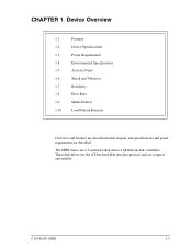
The MHN Series are compact and reliable. These disk drives use the AT-bus hard disk interface protocol and are 2.5-inch hard disk drives with built-in this chapter, and specifications and power requirement are described. CHAPTER 1 Device Overview 1.1 Features 1.2 Device Specifications 1.3 Power Requirements 1.4 Environmental Specifications 1.5 Acoustic Noise 1.6 Shock and Vibration 1.7 Reliability 1.8 Error Rate 1.9 Media Defects 1.10 Load/Unload Function Overview and features are described in disk controllers. C141-E120-02EN 1-1
The MHN Series are compact and reliable. These disk drives use the AT-bus hard disk interface protocol and are 2.5-inch hard disk drives with built-in this chapter, and specifications and power requirement are described. CHAPTER 1 Device Overview 1.1 Features 1.2 Device Specifications 1.3 Power Requirements 1.4 Environmental Specifications 1.5 Acoustic Noise 1.6 Shock and Vibration 1.7 Reliability 1.8 Error Rate 1.9 Media Defects 1.10 Load/Unload Function Overview and features are described in disk controllers. C141-E120-02EN 1-1
Manual/User Guide
Page 30
... be assigned, are not included in 107 seek operations. 1.9 Media Defects Defective sectors are replaced with access to the disk drive's error recovery procedure, and include read retries accompanying head offset operations. (2) Positioning error Positioning (seek) errors that cannot be... concerned with alternates when the disk (the MHN Series) are executed. • Hard Reset • Standby • Standby immediate • Sleep • Idle • Ldle immediate 1-10 C141-E120-02EN The product supports...
... be assigned, are not included in 107 seek operations. 1.9 Media Defects Defective sectors are replaced with access to the disk drive's error recovery procedure, and include read retries accompanying head offset operations. (2) Positioning error Positioning (seek) errors that cannot be... concerned with alternates when the disk (the MHN Series) are executed. • Hard Reset • Standby • Standby immediate • Sleep • Idle • Ldle immediate 1-10 C141-E120-02EN The product supports...
Manual/User Guide
Page 33
CHAPTER 2 Device Configuration 2.1 Device Configuration 2.2 System Configuration This chapter describes the internal configurations of the hard disk drives and the configuration of the systems in which they operate. C141-E120-02EN 2-1
CHAPTER 2 Device Configuration 2.1 Device Configuration 2.2 System Configuration This chapter describes the internal configurations of the hard disk drives and the configuration of the systems in which they operate. C141-E120-02EN 2-1

Manual/User Guide
Page 39
CHAPTER 3 Installation Conditions 3.1 Dimensions 3.2 Mounting 3.3 Cable Connections 3.4 Jumper Settings This chapter gives the external dimensions, installation conditions, surface temperature conditions, cable connections, and switch settings of the hard disk drives. C141-E144 C141-E120-02EN 3-1 For information about handling this hard disk drive and the system installation procedure, refer to the following Integration Guide.
CHAPTER 3 Installation Conditions 3.1 Dimensions 3.2 Mounting 3.3 Cable Connections 3.4 Jumper Settings This chapter gives the external dimensions, installation conditions, surface temperature conditions, cable connections, and switch settings of the hard disk drives. C141-E144 C141-E120-02EN 3-1 For information about handling this hard disk drive and the system installation procedure, refer to the following Integration Guide.
Manual/User Guide
Page 45
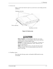
... the cover of the disk drive. Do not touch the printed circuit board, but hold it too hard, the cover and the spindle motor contact, which may cause damage to the disk drive. C141-E120-02EN 3-7 3.2 Mounting (5) Service area Figure 3.6 shows how the drive must be accessed (service areas...) during and after installation. Ensure that the disk drive is not affected ...
... the cover of the disk drive. Do not touch the printed circuit board, but hold it too hard, the cover and the spindle motor contact, which may cause damage to the disk drive. C141-E120-02EN 3-7 3.2 Mounting (5) Service area Figure 3.6 shows how the drive must be accessed (service areas...) during and after installation. Ensure that the disk drive is not affected ...
Manual/User Guide
Page 62
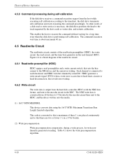
...or fewer 1's in a 17-bit border. (2) Write precompensation Write precompensation compensates, during self-calibration If the disk drive receives a command execution request from the hard disk controller (HDC) with the NRZ data format, and sent to the MR device and the current in the RDC...the encoder circuit in writing. Theory of Device Operation 4.5.3 Command processing during a write process, for a long time, even when the disk drive is performing self-calibration. The command execution wait time is a block diagram of the read/write circuit. 4.6.1 Read/write preamplifier (HDIC) ...
...or fewer 1's in a 17-bit border. (2) Write precompensation Write precompensation compensates, during self-calibration If the disk drive receives a command execution request from the hard disk controller (HDC) with the NRZ data format, and sent to the MR device and the current in the RDC...the encoder circuit in writing. Theory of Device Operation 4.5.3 Command processing during a write process, for a long time, even when the disk drive is performing self-calibration. The command execution wait time is a block diagram of the read/write circuit. 4.6.1 Read/write preamplifier (HDIC) ...
Manual/User Guide
Page 148
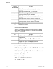
... unknown meaning. Bits 2 to 7: Reserved bits 5-72 C141-E120-02EN Self-test has been suspended by serbo test. Self-test has been completed abnormally by hard or soft reset. Bits 1 to 15: Reserved bits • Error logging capability Bit 0: Indicates that off -line read test. Self-test has been stopped by...
... unknown meaning. Bits 2 to 7: Reserved bits 5-72 C141-E120-02EN Self-test has been suspended by serbo test. Self-test has been completed abnormally by hard or soft reset. Bits 1 to 15: Reserved bits • Error logging capability Bit 0: Indicates that off -line read test. Self-test has been stopped by...

Manual/User Guide
Page 222
... command, the drive starts transferring data of sectors requested by the host system. When all data requested by the SET FEATURES command during unwritten data is kept, the instruction is not enabled until remaining unwritten data is disabled by the host are written on the disk medium. Even if a hard reset or... soft reset is received or the write cache function is written onto the disk medium. 6-20 C141-E120-02EN
... command, the drive starts transferring data of sectors requested by the host system. When all data requested by the SET FEATURES command during unwritten data is kept, the instruction is not enabled until remaining unwritten data is disabled by the host are written on the disk medium. Even if a hard reset or... soft reset is received or the write cache function is written onto the disk medium. 6-20 C141-E120-02EN

Manual/User Guide
Page 229
... DRDY DRQ DSC DWF dB A-scale weighting Disk enclosure Device/head register Drive ready Ddata request bit Drive seek complete Drive write fault E ECC Error checking and correction ER Error register ERR Error F FR Feature register H HA Host adapter HDD Hard disk drive I IDNF ID not found IRQ14 Interrupt request 14 L LED Light emitting diode...
... DRDY DRQ DSC DWF dB A-scale weighting Disk enclosure Device/head register Drive ready Ddata request bit Drive seek complete Drive write fault E ECC Error checking and correction ER Error register ERR Error F FR Feature register H HA Host adapter HDD Hard disk drive I IDNF ID not found IRQ14 Interrupt request 14 L LED Light emitting diode...


