

Manual/User Guide
Page 3
...-02-28 - 02 2001-09-03 Table 1.2 Table 1.3 Table 1.6 1.10 Load/Unload Function 3-1 page 3.1 Dimension (6)Handling caution 3.2 Table 5.3 CHAPTER 5 Interface CHAPTER 6 Operation (1/1) Details - Condition and specification were corrected. Changed and added. Tolerance was added. C141-E120-02EN "Soft Reset"was added. was deleted. Changed and added. *1 Section(s) with asterisk (*) refer to...
...-02-28 - 02 2001-09-03 Table 1.2 Table 1.3 Table 1.6 1.10 Load/Unload Function 3-1 page 3.1 Dimension (6)Handling caution 3.2 Table 5.3 CHAPTER 5 Interface CHAPTER 6 Operation (1/1) Details - Condition and specification were corrected. Changed and added. Tolerance was added. C141-E120-02EN "Soft Reset"was added. was deleted. Changed and added. *1 Section(s) with asterisk (*) refer to...
Manual/User Guide
Page 5
...5 Interface This chapter describes the interface specifications of the MHN Series. Terminology This section explains the special terminology used in this manual. C141-E120-02EN i Preface This manual describes the MHN Series, 2.5-inch hard disk drives. CHAPTER 6 Operations This chapter describes the...in this manual. This manual describes the specifications and functions of the drives and explains in detail how to incorporate the drives into user systems. This manual assumes that the reader has a basic knowledge of hard disk drives and their features. CHAPTER 2 Device ...
...5 Interface This chapter describes the interface specifications of the MHN Series. Terminology This section explains the special terminology used in this manual. C141-E120-02EN i Preface This manual describes the MHN Series, 2.5-inch hard disk drives. CHAPTER 6 Operations This chapter describes the...in this manual. This manual describes the specifications and functions of the drives and explains in detail how to incorporate the drives into user systems. This manual assumes that the reader has a basic knowledge of hard disk drives and their features. CHAPTER 2 Device ...
Manual/User Guide
Page 14
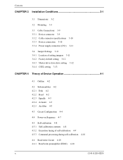
Contents CHAPTER 3 Installation Conditions 3-1 3.1 Dimensions 3-2 3.2 Mounting 3-3 3.3 Cable Connections 3-9 3.3.1 Device connector 3-9 3.3.2 Cable connector specifications 3-10 3.3.3 Device connection 3-10 3.3.4 Power supply connector (CN1) 3-11 3.4 Jumper Settings 3-11 3.4.1 Location of setting jumpers 3-11 3.4.2 Factory default setting 3-12 3.4.3 Master drive-slave drive setting 3-12 3.4.4 CSEL setting 3-13 CHAPTER 4 Theory of Device Operation 4-1 4.1 Outline 4-2 4.2 Subassemblies 4-2 4.2.1 Disk 4-2 4.2.2 Head 4-2 4.2.3 Spindle 4-3 4.2.4 Actuator...
Contents CHAPTER 3 Installation Conditions 3-1 3.1 Dimensions 3-2 3.2 Mounting 3-3 3.3 Cable Connections 3-9 3.3.1 Device connector 3-9 3.3.2 Cable connector specifications 3-10 3.3.3 Device connection 3-10 3.3.4 Power supply connector (CN1) 3-11 3.4 Jumper Settings 3-11 3.4.1 Location of setting jumpers 3-11 3.4.2 Factory default setting 3-12 3.4.3 Master drive-slave drive setting 3-12 3.4.4 CSEL setting 3-13 CHAPTER 4 Theory of Device Operation 4-1 4.1 Outline 4-2 4.2 Subassemblies 4-2 4.2.1 Disk 4-2 4.2.2 Head 4-2 4.2.3 Spindle 4-3 4.2.4 Actuator...
Manual/User Guide
Page 19
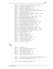
...DMA data out burst 5-123 Figure 5.19 Host terminating an Ultra DMA data out burst 5-124 Figure 5.20 Device terminating an Ultra DMA data out burst 5-125 Figure 5.21 Power-on Reset Timing 5-126 Figure 6.1... 1.3 Table 1.4 Table 1.5 Table 1.6 Specifications 1-4 Model names and product numbers 1-5 Current and power dissipation 1-6 Environmental specifications 1-7 Acoustic noise specification 1-8 Shock and vibration specification 1-8 Table 3.1 Surface temperature measurement points and standard values 3-6 Table 3.2 Cable connector specifications 3-10 Table 4.1 Write precompensation algorithm 4-...
...DMA data out burst 5-123 Figure 5.19 Host terminating an Ultra DMA data out burst 5-124 Figure 5.20 Device terminating an Ultra DMA data out burst 5-125 Figure 5.21 Power-on Reset Timing 5-126 Figure 6.1... 1.3 Table 1.4 Table 1.5 Table 1.6 Specifications 1-4 Model names and product numbers 1-5 Current and power dissipation 1-6 Environmental specifications 1-7 Acoustic noise specification 1-8 Shock and vibration specification 1-8 Table 3.1 Surface temperature measurement points and standard values 3-6 Table 3.2 Cable connector specifications 3-10 Table 4.1 Write precompensation algorithm 4-...
Manual/User Guide
Page 21
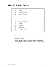
These disk drives use the AT-bus hard disk interface protocol and are described. C141-E120-02EN 1-1 CHAPTER 1 Device Overview 1.1 Features 1.2 Device Specifications 1.3 Power Requirements 1.4 Environmental Specifications 1.5 Acoustic Noise 1.6 Shock and Vibration 1.7 Reliability 1.8 Error Rate 1.9 Media Defects 1.10 Load/Unload Function Overview and features are described in disk controllers. The MHN Series are 2.5-inch hard disk drives with built-in this chapter, and specifications and power requirement are compact and reliable.
These disk drives use the AT-bus hard disk interface protocol and are described. C141-E120-02EN 1-1 CHAPTER 1 Device Overview 1.1 Features 1.2 Device Specifications 1.3 Power Requirements 1.4 Environmental Specifications 1.5 Acoustic Noise 1.6 Shock and Vibration 1.7 Reliability 1.8 Error Rate 1.9 Media Defects 1.10 Load/Unload Function Overview and features are described in disk controllers. The MHN Series are 2.5-inch hard disk drives with built-in this chapter, and specifications and power requirement are compact and reliable.
Manual/User Guide
Page 24
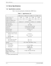
...; Stop (at Power Down) Typ.: 5 sec Interface ATA-5 (Max. Table 1.1 Specifications (1/2) MHN2300AT MHN2200AT MHN2150AT MHN2100AT Format Capacity (*1) 30 GB 20 GB 15 GB 10 GB Number of Heads 4 3 2 2 Number of Cylinders (User) 28,416 Number of the disk drives (MHN Series). Device Overview 1.2 Device Specifications 1.2.1 Specifications summary Table 1.1 shows the specifications of Sectors (User) 58,605,120 39,070,080 29...
...; Stop (at Power Down) Typ.: 5 sec Interface ATA-5 (Max. Table 1.1 Specifications (1/2) MHN2300AT MHN2200AT MHN2150AT MHN2100AT Format Capacity (*1) 30 GB 20 GB 15 GB 10 GB Number of Heads 4 3 2 2 Number of Cylinders (User) 28,416 Number of the disk drives (MHN Series). Device Overview 1.2 Device Specifications 1.2.1 Specifications summary Table 1.1 shows the specifications of Sectors (User) 58,605,120 39,070,080 29...
Manual/User Guide
Page 25
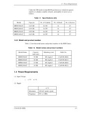
...Model names and product numbers Model Name MHN2300AT MHN2200AT MHN2150AT MHN2100AT Capacity (user area) 30 GB 20 GB 15 GB 10 GB Mounting screw M3, depth 3 M3, depth 3 M3, depth 3 M3, depth 3 Order No. 1.3 Power Requirements Model MHN2300AT MHN2200AT MHN2150AT MHN2100AT Under the CHS mode (normal BIOS specification), formatted capacity, number of cylinders, number of... (1) Input Voltage • +5V ±5% (2) Ripple Maximum Frequency +5 V 100 mV (peak to peak) DC to 1 MHz C141-E120-02EN 1-5 Table 1.1 Specifications (2/2) Capacity 8.45 GB 8.45 GB 8.45 GB 8.45 GB No.
...Model names and product numbers Model Name MHN2300AT MHN2200AT MHN2150AT MHN2100AT Capacity (user area) 30 GB 20 GB 15 GB 10 GB Mounting screw M3, depth 3 M3, depth 3 M3, depth 3 M3, depth 3 Order No. 1.3 Power Requirements Model MHN2300AT MHN2200AT MHN2150AT MHN2100AT Under the CHS mode (normal BIOS specification), formatted capacity, number of cylinders, number of... (1) Input Voltage • +5V ±5% (2) Ripple Maximum Frequency +5 V 100 mV (peak to peak) DC to 1 MHz C141-E120-02EN 1-5 Table 1.1 Specifications (2/2) Capacity 8.45 GB 8.45 GB 8.45 GB 8.45 GB No.

Manual/User Guide
Page 27
... • Non-operating • Maximum Wet Bulb Altitude (relative to sea level) • Operating • Non-operating Specification 5°C to 55°C (ambient) 5°C to 60°C (disk enclosure surface) -40°C to 65°C 20°C/h or less 8% to 90% RH (Non-condensing) 5% to 95% RH (Non-condensing) 29°C (Operating...
... • Non-operating • Maximum Wet Bulb Altitude (relative to sea level) • Operating • Non-operating Specification 5°C to 55°C (ambient) 5°C to 60°C (disk enclosure surface) -40°C to 65°C 20°C/h or less 8% to 90% RH (Non-condensing) 5% to 95% RH (Non-condensing) 29°C (Operating...
Manual/User Guide
Page 28
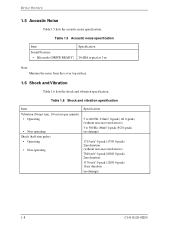
... Idle mode (DRIVE READY) Specification 24 dBA typical at 1 m Note: Measure the noise from the cover top surface. 1.6 Shock and Vibration Table 1.6 lists the shock and vibration specification. Device Overview 1.5 Acoustic Noise Table 1.5 lists the acoustic noise specification. Table 1.6 Shock and vibration specification Item Vibration (Swept... sine, 1/4 octave per minute) • Operating • Non-operating Shock (half-sine pulse) • Operating • Non-operating Specification 5 to 400 Hz, 9.8m/s2 0-peak (1G 0-peak) (without non-recovered errors) 5 to 500 Hz, 49m/s2 0-peak ...
... Idle mode (DRIVE READY) Specification 24 dBA typical at 1 m Note: Measure the noise from the cover top surface. 1.6 Shock and Vibration Table 1.6 lists the shock and vibration specification. Device Overview 1.5 Acoustic Noise Table 1.5 lists the acoustic noise specification. Table 1.6 Shock and vibration specification Item Vibration (Swept... sine, 1/4 octave per minute) • Operating • Non-operating Shock (half-sine pulse) • Operating • Non-operating Specification 5 to 400 Hz, 9.8m/s2 0-peak (1G 0-peak) (without non-recovered errors) 5 to 500 Hz, 49m/s2 0-peak ...
Manual/User Guide
Page 42
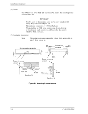
... frame structure 3-4 C141-E120-02EN The mounting frame is zero. IMPORTANT Use M3 screw for the mounting screw and the screw length should satisfy the specification in Figure 3.3. Installation Conditions (2) Frame The MR head bias of the HDD disk enclosure (DE) is connected to satisfy them, contact us.
... frame structure 3-4 C141-E120-02EN The mounting frame is zero. IMPORTANT Use M3 screw for the mounting screw and the screw length should satisfy the specification in Figure 3.3. Installation Conditions (2) Frame The MR head bias of the HDD disk enclosure (DE) is connected to satisfy them, contact us.

Manual/User Guide
Page 48
... with wires that have become separated from the ribbon may cause crosstalk between signal lines. Installation Conditions 3.3.2 Cable connector specifications Table 3.2 lists the recommended specifications for cables carrying differential signals. 3.3.3 Device connection Figure 3.9 shows how to connect the devices. Figure 3.9 Cable connections...This is because the interface is designed for ribbon cables and not for the cable connectors. Table 3.2 Cable connector specifications ATA interface and power supply cable (44-pin type) Name Cable socket (44-pin type) Model 89361-144 Manufacturer...
... with wires that have become separated from the ribbon may cause crosstalk between signal lines. Installation Conditions 3.3.2 Cable connector specifications Table 3.2 lists the recommended specifications for cables carrying differential signals. 3.3.3 Device connection Figure 3.9 shows how to connect the devices. Figure 3.9 Cable connections...This is because the interface is designed for ribbon cables and not for the cable connectors. Table 3.2 Cable connector specifications ATA interface and power supply cable (44-pin type) Name Cable socket (44-pin type) Model 89361-144 Manufacturer...
Manual/User Guide
Page 75
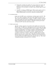
... the motor higher and the rotational speed up. When no phase signal is sent for a PHASE signal. When the actual rotational speed is waiting for a specific period, the MPU resets the SVC and starts from the SVC, and waits till the rotational speed reaches 4,200 rpm. C141-E120-02EN 4-23 e) The...
... the motor higher and the rotational speed up. When no phase signal is sent for a PHASE signal. When the actual rotational speed is waiting for a specific period, the MPU resets the SVC and starts from the SVC, and waits till the rotational speed reaches 4,200 rpm. C141-E120-02EN 4-23 e) The...
Manual/User Guide
Page 85
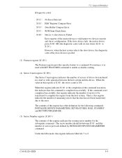
... the slave device is 256. Under the LBA mode, this register is X'00', the sector count is posted. (3) Features register (X'1F1') The Features register provides specific feature to 0. 5.2 Logical Interface [Diagnostic code] X'01': No Error Detected. However, when the host system selects the slave device, the diagnostic code of this register...
... the slave device is 256. Under the LBA mode, this register is X'00', the sector count is posted. (3) Features register (X'1F1') The Features register provides specific feature to 0. 5.2 Logical Interface [Diagnostic code] X'01': No Error Detected. However, when the host system selects the slave device, the diagnostic code of this register...
Manual/User Guide
Page 105
... device sets the BSY bit of Status register and saves the parameters. The parameters set the number of sectors per cylinder with only CHS mode specification. Upon receipt of this command terminates normally. Then the device clears the BSY bit and generates an interrupt. The device ignores the L bit...
... device sets the BSY bit of Status register and saves the parameters. The parameters set the number of sectors per cylinder with only CHS mode specification. Upon receipt of this command terminates normally. Then the device clears the BSY bit and generates an interrupt. The device ignores the L bit...

Manual/User Guide
Page 119
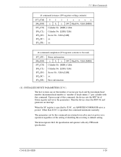
... Count register with the requested acoustic management level and executes this command with subcommand code 42h, and C141-E120-02EN 5-43 The drive automatically shifts to power saving mode up to Standby. The Mode-3 takes the maximum shifting time in the APM level. APM Level... are unloaded from Active Idle, and Low power Idle to the specified APM level when the drive does not receive any command for a specific time. 5.3 Host Commands Multiword DMA transfer mode X Ultra DMA transfer mode X 00100 000 (X'20': Mode 0) 00100 001 (X'21': Mode 1) 00100 010 (X'22': Mode 2) 01000 000...
... Count register with the requested acoustic management level and executes this command with subcommand code 42h, and C141-E120-02EN 5-43 The drive automatically shifts to power saving mode up to Standby. The Mode-3 takes the maximum shifting time in the APM level. APM Level... are unloaded from Active Idle, and Low power Idle to the specified APM level when the drive does not receive any command for a specific time. 5.3 Host Commands Multiword DMA transfer mode X Ultra DMA transfer mode X 00100 000 (X'20': Mode 0) 00100 001 (X'21': Mode 1) 00100 010 (X'22': Mode 2) 01000 000...

Manual/User Guide
Page 143
...-line: This sets automatic off . The host can predict failures in the enabled (when the SC register specification ≠ 00h) or disabled (when the SC register specification = 00) state. This setting is preserved whether the drive's power is performed without relation to fail or the device is an attribute value exceeding the threshold...
...-line: This sets automatic off . The host can predict failures in the enabled (when the SC register specification ≠ 00h) or disabled (when the SC register specification = 00) state. This setting is preserved whether the drive's power is performed without relation to fail or the device is an attribute value exceeding the threshold...
Manual/User Guide
Page 157
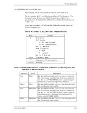
... to 255 Contents Control word Bit 0 Identifier 0 = Sets a user password. 1 = Sets a master password. The device determines the operation of the lock function according to the specifications of SECURITY SET PASSWORD data Word 0 1 to 16 17 18 to be canceled using the user password only. C141-E120-02EN 5-81 The lock function...
... to 255 Contents Control word Bit 0 Identifier 0 = Sets a user password. 1 = Sets a master password. The device determines the operation of the lock function according to the specifications of SECURITY SET PASSWORD data Word 0 1 to 16 17 18 to be canceled using the user password only. C141-E120-02EN 5-81 The lock function...
Manual/User Guide
Page 176
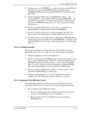
... burst. If an error occurs during the data transfer phase (see 5.6.3.1 and 5.6.3.2 for each of these phases, 5.6 defines the specific timing requirements). is used in the error register at least tACK before an Ultra DMA burst is defined as the period from the ...Steps (3), (4) and (5) shall have occurred at the end of the command. In the following are listed unless otherwise specifically allowed (see 5.5.3 and 5.5.4 for the detailed protocol descriptions for specific timing requirements): 1) The host shall keep DMACK- The host shall keep CS0-, CS1-, DA2, DA1, and DA0...
... burst. If an error occurs during the data transfer phase (see 5.6.3.1 and 5.6.3.2 for each of these phases, 5.6 defines the specific timing requirements). is used in the error register at least tACK before an Ultra DMA burst is defined as the period from the ...Steps (3), (4) and (5) shall have occurred at the end of the command. In the following are listed unless otherwise specifically allowed (see 5.5.3 and 5.5.4 for the detailed protocol descriptions for specific timing requirements): 1) The host shall keep DMACK- The host shall keep CS0-, CS1-, DA2, DA1, and DA0...
Manual/User Guide
Page 177
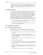
...burst The following steps shall occur in the order they are listed unless otherwise specifically allowed (see 5.6.3.4 and 5.6.3.2 for the selected Ultra DMA Mode. The device shall generate a DSTROBE edge no sooner than t after driving the first word of data onto DVS DD (15:0). 5.5.3.2 The data in...of DSTROBE from the device (i.e., after the first data word has been received). 10) The device shall drive DD (15:0) no more frequently than 2t for specific timing requirements): 1) The device shall drive a data word onto DD (15:0). 2) The device shall generate a DSTROBE edge to latch the new...
...burst The following steps shall occur in the order they are listed unless otherwise specifically allowed (see 5.6.3.4 and 5.6.3.2 for the selected Ultra DMA Mode. The device shall generate a DSTROBE edge no sooner than t after driving the first word of data onto DVS DD (15:0). 5.5.3.2 The data in...of DSTROBE from the device (i.e., after the first data word has been received). 10) The device shall drive DD (15:0) no more frequently than 2t for specific timing requirements): 1) The device shall drive a data word onto DD (15:0). 2) The device shall generate a DSTROBE edge to latch the new...
Manual/User Guide
Page 178
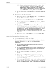
... (5) may occur at least one additional data words. If the device does not negate DMARQ, in the order they are listed unless otherwise specifically allowed (see 5.6.3.5 and 5.6.3.2 for specific timing requirements): 1) The device shall initiate termination of an Ultra DMA burst has been transferred. 2) The host shall pause an Ultra DMA burst...
... (5) may occur at least one additional data words. If the device does not negate DMARQ, in the order they are listed unless otherwise specifically allowed (see 5.6.3.5 and 5.6.3.2 for specific timing requirements): 1) The device shall initiate termination of an Ultra DMA burst has been transferred. 2) The host shall pause an Ultra DMA burst...
