
Installing a SATA Optical Drive
Page 1
Dell™ PowerEdge™ 19x0 and 29x0 Systems Installing a SATA Optical Drive
Dell™ PowerEdge™ 19x0 and 29x0 Systems Installing a SATA Optical Drive

Installing a SATA Optical Drive
Page 3
.... b Remove the center fans and the center fan bracket. See "Removing the Bezel" in your Hardware Owner's Manual for specific step instructions. Installing a SATA Optical Drive These instructions apply to Dell™ PowerEdge™ systems to remove the system cover and access any of the components inside the system. Removing an Existing Optical...
.... b Remove the center fans and the center fan bracket. See "Removing the Bezel" in your Hardware Owner's Manual for specific step instructions. Installing a SATA Optical Drive These instructions apply to Dell™ PowerEdge™ systems to remove the system cover and access any of the components inside the system. Removing an Existing Optical...
Installing a SATA Optical Drive
Page 4
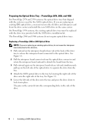
... with the system is used for the SATA optical drive. See Figure 1-1. 5 Lower the left side of the optical drive to the optical drive. PowerEdge 2970, 2950, and 1950 For PowerEdge 2970 and 2950 systems, the optical drive tray that shipped with the SATA drive installation kit. Replacing a PowerEdge 2950 or 2970 Optical Drive NOTE: If you are replacing an existing IDE...
... with the system is used for the SATA optical drive. See Figure 1-1. 5 Lower the left side of the optical drive to the optical drive. PowerEdge 2970, 2950, and 1950 For PowerEdge 2970 and 2950 systems, the optical drive tray that shipped with the SATA drive installation kit. Replacing a PowerEdge 2950 or 2970 Optical Drive NOTE: If you are replacing an existing IDE...

Installing a SATA Optical Drive
Page 5
Spread the side rails of the replacement drive tray and insert the back end of the drive. Installing a SATA Optical Drive 5 Replacing the Optical Drive in a PowerEdge 2950 or 2970 System 2 1 3 4 5 6 7 1 optical drive 3 interposer 5 SATA power cable 7 optical drive carrier 2 interposer release latch 4 SATA cable 6 carrier latch Replacing a PowerEdge 1950 Optical Drive NOTE: The replacement drive tray provided in the installation kit...
Spread the side rails of the replacement drive tray and insert the back end of the drive. Installing a SATA Optical Drive 5 Replacing the Optical Drive in a PowerEdge 2950 or 2970 System 2 1 3 4 5 6 7 1 optical drive 3 interposer 5 SATA power cable 7 optical drive carrier 2 interposer release latch 4 SATA cable 6 carrier latch Replacing a PowerEdge 1950 Optical Drive NOTE: The replacement drive tray provided in the installation kit...

Installing a SATA Optical Drive
Page 6
... SATA_A connector on the system board. a Route the cable through the power cable cutout in a PowerEdge 1950 Drive Tray 2 3 1 4 5 1 optical drive 3 SATA power cable 5 optical drive carrier 2 SATA cable 4 carrier latch Installing the SATA Optical Drive - Installing a SATA Optical Drive in the fan bracket and follow the power cable routing to the back of the chipset...
... SATA_A connector on the system board. a Route the cable through the power cable cutout in a PowerEdge 1950 Drive Tray 2 3 1 4 5 1 optical drive 3 SATA power cable 5 optical drive carrier 2 SATA cable 4 carrier latch Installing the SATA Optical Drive - Installing a SATA Optical Drive in the fan bracket and follow the power cable routing to the back of the chipset...

Installing a SATA Optical Drive
Page 7
...Installing a SATA Optical Drive 7 PowerEdge 2970 or 2950 1 Insert the optical drive tray into the system until it is fully inserted and locked into position. 2 Connect the SATA cable (the end with the branching power cable) to the back of the optical drive. 3 Connect the branching...to the power supply connector. See "Closing the System" in your Hardware Owner's Manual. 6 Close the system. Installing the SATA Optical Drive - See "SAS Controller Daughter Card" in the PowerEdge 1950 2 1 3 4 6 5 1 SATA data cable 3 chipset shroud 5 SATA power cable 2 SATA_A connector on the system ...
...Installing a SATA Optical Drive 7 PowerEdge 2970 or 2950 1 Insert the optical drive tray into the system until it is fully inserted and locked into position. 2 Connect the SATA cable (the end with the branching power cable) to the back of the optical drive. 3 Connect the branching...to the power supply connector. See "Closing the System" in your Hardware Owner's Manual. 6 Close the system. Installing the SATA Optical Drive - See "SAS Controller Daughter Card" in the PowerEdge 1950 2 1 3 4 6 5 1 SATA data cable 3 chipset shroud 5 SATA power cable 2 SATA_A connector on the system ...

Installing a SATA Optical Drive
Page 8
... Shroud" in your Hardware Owner's Manual. 5 Remove the cable retention bracket from the chassis slots. 6 Route the SATA cable in the cable channel in the PowerEdge 2950 and 2970 1 2 3 4 5 1 SATA_B connector on the system board. See Figure 1-4. 7 Route the SATA cable along the top of the system until the bracket detaches from... behind the central riser and connect the cable to the SATA_B connector on system board 2 cable retention bracket 3 SATA data cable 4 SATA power cable 5 optical drive 8 Installing a SATA Optical...
... Shroud" in your Hardware Owner's Manual. 5 Remove the cable retention bracket from the chassis slots. 6 Route the SATA cable in the cable channel in the PowerEdge 2950 and 2970 1 2 3 4 5 1 SATA_B connector on the system board. See Figure 1-4. 7 Route the SATA cable along the top of the system until the bracket detaches from... behind the central riser and connect the cable to the SATA_B connector on system board 2 cable retention bracket 3 SATA data cable 4 SATA power cable 5 optical drive 8 Installing a SATA Optical...

Installing a SATA Optical Drive
Page 9
...system and attached peripherals. See Figure 1-5. - PowerEdge 2900 and 1900 1 If the mounting screws are not attached to the drive, install them now. 2 Align the mounting screws with the bay slide slots and insert the optical drive into the optical drive bay until the spring latch engages. 3 ... the other to an available power supply cable. 5 Replace the center fan bracket. For a PowerEdge 1900, use the SATA_B connector. - Installing a SATA Optical Drive 9 See "Closing the System" in your Hardware Owner's Manual. 11 Reconnect the system to the CD/TBU connector on the system board...
...system and attached peripherals. See Figure 1-5. - PowerEdge 2900 and 1900 1 If the mounting screws are not attached to the drive, install them now. 2 Align the mounting screws with the bay slide slots and insert the optical drive into the optical drive bay until the spring latch engages. 3 ... the other to an available power supply cable. 5 Replace the center fan bracket. For a PowerEdge 1900, use the SATA_B connector. - Installing a SATA Optical Drive 9 See "Closing the System" in your Hardware Owner's Manual. 11 Reconnect the system to the CD/TBU connector on the system board...

Installing a SATA Optical Drive
Page 10
Figure 1-5. SATA Cable Routing in your Hardware Owner's Manual. 10 Reconnect the system to the SAS controller daughter card. 9 Close the system. See "Closing the System" in a PowerEdge 2900 or 1900 3 2 4 5 1 1 optical drive 3 SATA data cable 5 SATA power connector on SAS backplane (PowerEdge 2900 only) 2 SATA power cable 4 SATA connector on system board 8 Reconnect the cables to power and turn on the system and attached peripherals. 10 Installing a SATA Optical Drive
Figure 1-5. SATA Cable Routing in your Hardware Owner's Manual. 10 Reconnect the system to the SAS controller daughter card. 9 Close the system. See "Closing the System" in a PowerEdge 2900 or 1900 3 2 4 5 1 1 optical drive 3 SATA data cable 5 SATA power connector on SAS backplane (PowerEdge 2900 only) 2 SATA power cable 4 SATA connector on system board 8 Reconnect the cables to power and turn on the system and attached peripherals. 10 Installing a SATA Optical Drive

Information Update
Page 6
... data rates, and iSCSI remote boot. • Support for 10-Gb Ethernet cards. • One internal USB 2.0-compliant connector supporting an optional bootable USB flash drive or USB memory key. • Support for optional SAS 6i/R and PERC 6/i adapters. The USB memory key can be enabled in the Hardware Owner's Manual...
... data rates, and iSCSI remote boot. • Support for 10-Gb Ethernet cards. • One internal USB 2.0-compliant connector supporting an optional bootable USB flash drive or USB memory key. • Support for optional SAS 6i/R and PERC 6/i adapters. The USB memory key can be enabled in the Hardware Owner's Manual...
Information Update
Page 9
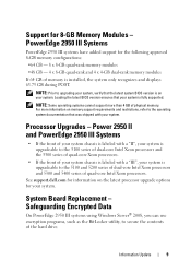
... BIOS version is fully supported. Power 2950 II and PowerEdge 2950 III Systems • If the front...of quad-core Intel Xeon processors. Processor Upgrades - Safeguarding Encrypted Data On PowerEdge 2950 III systems using Windows Server® 2008, you can use encryption programs... your system, verify that your system is on your system. PowerEdge 2950 III Systems PowerEdge 2950 III systems have added support for your system. For more than...that was shipped with a "III", your system. See support.dell.com for information on memory support requirements and restrictions, refer to...
... BIOS version is fully supported. Power 2950 II and PowerEdge 2950 III Systems • If the front...of quad-core Intel Xeon processors. Processor Upgrades - Safeguarding Encrypted Data On PowerEdge 2950 III systems using Windows Server® 2008, you can use encryption programs... your system, verify that your system is on your system. PowerEdge 2950 III Systems PowerEdge 2950 III systems have added support for your system. For more than...that was shipped with a "III", your system. See support.dell.com for information on memory support requirements and restrictions, refer to...
Information Update
Page 10
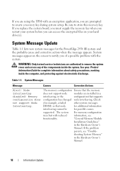
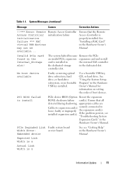
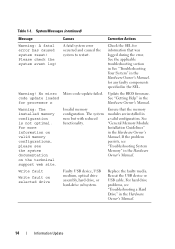
...or the configuration that supports configuration has changed node interleaving. System messages appear on your Product Information Guide for the PowerEdge 2950 III system and the probable cause and corrective action when the message appears. The memory configuration Ensure that node ... with the system. "General Memory Module Installation Guidelines" in the Hardware Owner's Manual. 10 Information Update See your hard drive(s). Check (for possible causes. Node Interleaving disabled! supported. Table 1-1. WARNING: Only trained service technicians are authorized to store...
...or the configuration that supports configuration has changed node interleaving. System messages appear on your Product Information Guide for the PowerEdge 2950 III system and the probable cause and corrective action when the message appears. The memory configuration Ensure that node ... with the system. "General Memory Module Installation Guidelines" in the Hardware Owner's Manual. 10 Information Update See your hard drive(s). Check (for possible causes. Node Interleaving disabled! supported. Table 1-1. WARNING: Only trained service technicians are authorized to store...
Information Update
Page 11
No boot device available Faulty or missing optical drive subsystem, hard drive, or hard-drive subsystem, or no bootable USB key installed. Ensure that the Remote Access Controller is installed in the internal SAS controller the dedicated storage in the ... a RAC Card" in the Hardware Owner's Manual. If the problem persists, see "Getting Help" in the Internal_Storage slot! Use a bootable USB key, CD, or hard drive. PCI BIOS failed to loose; Expected Link Width is n Actual Link Width is n Information Update 11 See "Using the System Setup Program" in the dedicated...
No boot device available Faulty or missing optical drive subsystem, hard drive, or hard-drive subsystem, or no bootable USB key installed. Ensure that the Remote Access Controller is installed in the internal SAS controller the dedicated storage in the ... a RAC Card" in the Hardware Owner's Manual. If the problem persists, see "Getting Help" in the Internal_Storage slot! Use a bootable USB key, CD, or hard drive. PCI BIOS failed to loose; Expected Link Width is n Actual Link Width is n Information Update 11 See "Using the System Setup Program" in the dedicated...
Information Update
Page 14
...update failed. Update the BIOS firmware. Invalid memory configuration. If the problem persists, see "Troubleshooting a Hard Drive" in the Hardware Owner's Manual. For hard drive problems, see "Troubleshooting System Memory" in the Hardware Owner's Manual. 14 Information Update See the applicable ...Manual. For more information on valid memory configurations, please see the system documentation on selected drive Faulty USB device, USB medium, optical drive assembly, hard drive, or hard-drive subsystem. Ensure that was logged during the error. Check the SEL for information that the...
...update failed. Update the BIOS firmware. Invalid memory configuration. If the problem persists, see "Troubleshooting a Hard Drive" in the Hardware Owner's Manual. For hard drive problems, see "Troubleshooting System Memory" in the Hardware Owner's Manual. 14 Information Update See the applicable ...Manual. For more information on valid memory configurations, please see the system documentation on selected drive Faulty USB device, USB medium, optical drive assembly, hard drive, or hard-drive subsystem. Ensure that was logged during the error. Check the SEL for information that the...
Information Update
Page 24
... the System Build and Update Utility, Microsoft® Windows® 2000 is supported by the PowerEdge 2950 and 2950 II systems, but not by the PowerEdge 2950 III system. System Support for Microsoft Windows 2000 If you to a hard drive. 24 Information Update System Diagnostics Update In the Customize window of operating systems on the Server...
... the System Build and Update Utility, Microsoft® Windows® 2000 is supported by the PowerEdge 2950 and 2950 II systems, but not by the PowerEdge 2950 III system. System Support for Microsoft Windows 2000 If you to a hard drive. 24 Information Update System Diagnostics Update In the Customize window of operating systems on the Server...

Information Update
Page 36
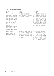
... information on valid memory configurations, please see the system documentation on the technical support web site. 降低。 Write fault Write fault on selected drive USB 设备、 USB USB 设备或 USB 36 信息更新 表 1-1 信息 原因 纠正措施 Warning...
... information on valid memory configurations, please see the system documentation on the technical support web site. 降低。 Write fault Write fault on selected drive USB 设备、 USB USB 设备或 USB 36 信息更新 表 1-1 信息 原因 纠正措施 Warning...

Information Update
Page 120
表 1-1 原因 対応処置 Warning! For more information on valid memory configurations, please see the system documentation on selected drive USB USB USB USB 120 Write fault Write fault on the technical support web site. No micro code update loaded for processor n BIOS ださい。 Warning: The installed memory configuration is not optimal.
表 1-1 原因 対応処置 Warning! For more information on valid memory configurations, please see the system documentation on selected drive USB USB USB USB 120 Write fault Write fault on the technical support web site. No micro code update loaded for processor n BIOS ださい。 Warning: The installed memory configuration is not optimal.
Information Update
Page 146
표 1-1 메시지 Warning: The installed memory configuration is not optimal. For more information on valid memory configurations, please see the system documentation on selected drive 원인 시오 . USB 장치 , USB USB USB 146 Write fault Write fault on the technical support web site.
표 1-1 메시지 Warning: The installed memory configuration is not optimal. For more information on valid memory configurations, please see the system documentation on selected drive 원인 시오 . USB 장치 , USB USB USB 146 Write fault Write fault on the technical support web site.

Getting Started Guide
Page 5
... upgrade kit from Dell. NOTE: DVD devices are installed. • Support for up to six 3.5-inch, internal hot-pluggable Serial Attached SCSI (SAS) or SATA hard drives without optional media bay, or up to four 3.5-inch internal hot-pluggable SAS or SATA hard drives with optional media ...switch that supports multiprocessing. SMP greatly improves overall system performance by installing a second processor, you must order the processor upgrade kits from Dell contains the correct version of the processor, heat sink, and fan as well as additional processors. Not all versions of the Intel ...
... upgrade kit from Dell. NOTE: DVD devices are installed. • Support for up to six 3.5-inch, internal hot-pluggable Serial Attached SCSI (SAS) or SATA hard drives without optional media bay, or up to four 3.5-inch internal hot-pluggable SAS or SATA hard drives with optional media ...switch that supports multiprocessing. SMP greatly improves overall system performance by installing a second processor, you must order the processor upgrade kits from Dell contains the correct version of the processor, heat sink, and fan as well as additional processors. Not all versions of the Intel ...
Getting Started Guide
Page 6
... about booting from an external device attached to eight 2.5-inch SAS or six 3.5-inch SATA hard drives. See support.dell.com for the latest support information about specific features, see "Technical Specifications" on the back) capable of supporting a diskette... drive, a CD-ROM drive, a keyboard, a mouse, or a USB flash drive. • Optional remote access controller (RAC) for remote systems management. • An integrated VGA-...
... about booting from an external device attached to eight 2.5-inch SAS or six 3.5-inch SATA hard drives. See support.dell.com for the latest support information about specific features, see "Technical Specifications" on the back) capable of supporting a diskette... drive, a CD-ROM drive, a keyboard, a mouse, or a USB flash drive. • Optional remote access controller (RAC) for remote systems management. • An integrated VGA-...


